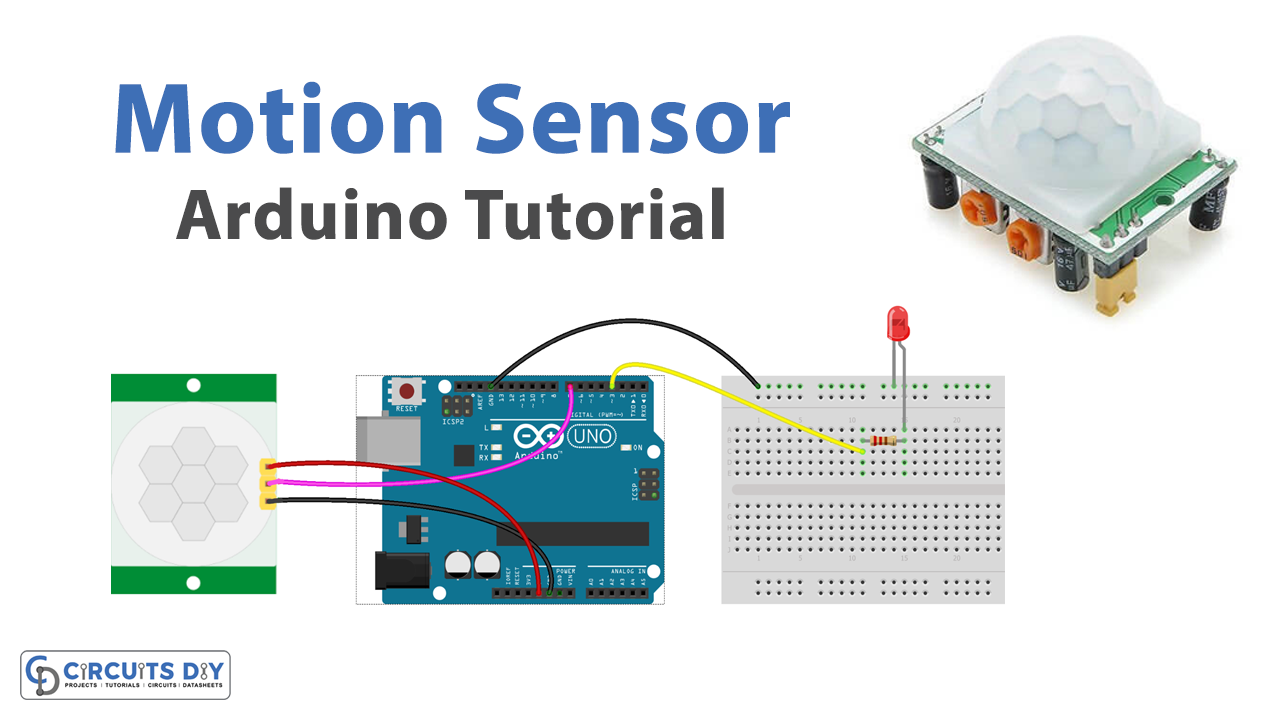
Introduction
A PIR motion sensor-controlled LED with an Arduino UNO microcontroller is a system that uses a PIR motion sensor to detect motion and an Arduino UNO microcontroller to control an LED based on the presence or absence of motion.
PIR motion sensors, also known as pyroelectric infrared sensors, are devices that detect motion by sensing changes in the infrared radiation levels in their surroundings. They have a built-in pyroelectric sensor and a Fresnel lens that concentrates the infrared radiation onto the sensor. When the sensor detects a change in the infrared radiation levels, it outputs a digital signal on its output pin.
Hardware Components
You will require the following hardware for Motion Sensor with Arduino.
| S.no | Component | Value | Qty |
|---|---|---|---|
| 1. | Arduino UNO | – | 1 |
| 2. | USB Cable Type A to B | – | 1 |
| 3. | Motion Sensor | HC-SR501 | 1 |
| 4. | Power Adapter for Arduino | 9V | 1 |
| 5. | LED | – | 1 |
| 6. | Resistor | Ω | 1 |
| 7. | Breadboard | – | 1 |
| 8. | Jumper Wires | – | 1 |
Motion Sensor with Arduino UNO
- Connect the HC-SR501 PIR motion sensor to the Arduino according to the sensor’s documentation. Typically, the HC-SR501 PIR motion sensor has four pins: VCC, GND, OUT, and ADJ. The VCC pin should be connected to the 5V power pin on the Arduino, the GND pin should be connected to one of the GND pins on the Arduino, the OUT pin should be connected to a digital input pin on the Arduino, such as pin 2 or 3, and the ADJ pin should be connected to a potentiometer or a fixed resistor to adjust the sensitivity of the sensor.
- Connect the LED to the Arduino according to the LED’s documentation. Typically, the LED has two pins: an anode and a cathode. The anode, which is the longer pin, should be connected to a digital output pin on the Arduino, such as pin 8 or 9, and the cathode, which is the shorter pin, should be connected to a GND pin on the Arduino.
- Open the Arduino Integrated Development Environment (IDE) on your computer and create a new sketch.
- At the top of the sketch, define the pin numbers for the HC-SR501 PIR motion sensor and LED as constants. This allows the code to reference the pins by name rather than by number, which can make the code easier to read and understand. For example:
const int motionPin = 2;   // HC-SR501 PIR motion sensor pin
const int ledPin = 8;   // LED pin
- In the setup function, set the pin modes for the HC-SR501 PIR motion sensor and LED pins using the
pinModefunction. This tells the Arduino which functions the pins will be used for, such as input or output. For example:
pinMode(motionPin, INPUT);   // Set HC-SR501 PIR motion sensor pin as input
pinMode(ledPin, OUTPUT);  // Set LED pin as output
- In the loop function, read the state of the HC-SR501 PIR motion sensor using the
digitalReadfunction. ThedigitalReadfunction returns the state of the pin as a HIGH or LOW value. For example:
int motionState = digitalRead(motionPin); // Read HC-SR501 PIR motion sensor state
- If the HC-SR501 PIR motion sensor is triggered, turn the LED on using the
digitalWritefunction. ThedigitalWritefunction sets the state of the LED pin to HIGH, which turns the LED on. For example:
if (motionState == HIGH) {   // If HC-SR501 PIR motion sensor is triggered
  digitalWrite(ledPin, HIGH);  // Turn LED on
}
- If the HC-SR501 PIR motion sensor is not triggered, turn the LED off using the
digitalWritefunction. ThedigitalWritefunction sets the state of the LED pin to LOW, which turns the LED off. For example:
else {  // If HC-SR501 PIR motion sensor is not triggered
  digitalWrite(ledPin, LOW);  // Turn LED off
}
Schematic
Make connections according to the circuit diagram given below.
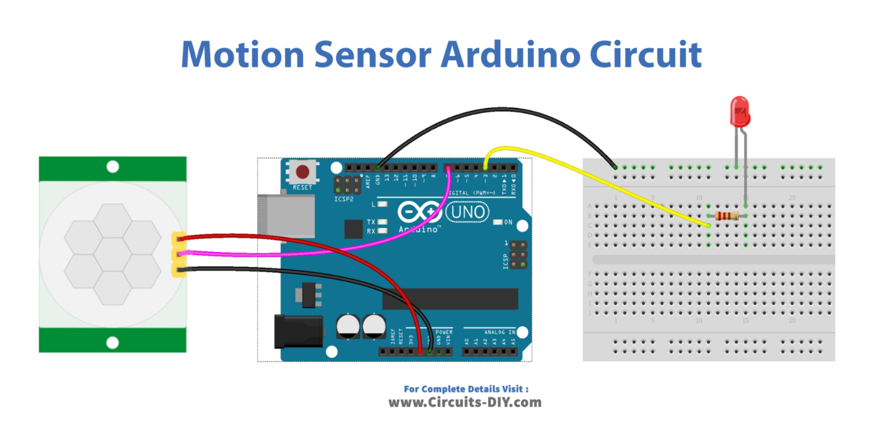
Wiring / Connections
| Arduino | Motion Sensor |
|---|---|
| 5V | VCC |
| GND | GND |
| D7 | OUT |
Installing Arduino IDE
First, you need to install Arduino IDE Software from its official website Arduino. Here is a simple step-by-step guide on “How to install Arduino IDE“.
Code
Now copy the following code and upload it to Arduino IDE Software.
const int MOTION_SENSOR_PIN = 7;   // Arduino pin connected to the OUTPUT pin of motion sensor
const int LED_PIN           = 3;   // Arduino pin connected to LED's pin
int motionStateCurrent      = LOW; // current  state of motion sensor's pin
int motionStatePrevious     = LOW; // previous state of motion sensor's pin

void setup() {
  Serial.begin(9600);                // initialize serial
  pinMode(MOTION_SENSOR_PIN, INPUT); // set arduino pin to input mode
  pinMode(LED_PIN, OUTPUT);          // set arduino pin to output mode
}

void loop() {
  motionStatePrevious = motionStateCurrent;             // store old state
  motionStateCurrent  = digitalRead(MOTION_SENSOR_PIN); // read new state

  if (motionStatePrevious == LOW && motionStateCurrent == HIGH) { // pin state change: LOW -> HIGH
    Serial.println("Motion detected!");
    digitalWrite(LED_PIN, HIGH); // turn on
  }
  else
  if (motionStatePrevious == HIGH && motionStateCurrent == LOW) { // pin state change: HIGH -> LOW
    Serial.println("Motion stopped!");
    digitalWrite(LED_PIN, LOW);  // turn off
  }
}
Working Explanation
The working of a PIR-controlled LED circuit is broken down between the void setup( ) and void loop( ) functions. The setup function is executed once when the program begins. It is used to set up the input and output pins and any other necessary configurations. In this case, the setup function uses the pinMode function to set the PIR motion sensor pin as an input and the LED pin as an output. This ensures that the microcontroller is ready to receive input from the sensor and control the LED.
The loop function is executed repeatedly in a loop until the program is stopped. It is used to read the input from the PIR motion sensor and control the LED based on the input received. In this case, the loop function uses the digitalRead function to read the state of the PIR motion sensor. If the sensor is triggered, the if statement evaluates to true and the LED is turned on using the digitalWrite function. If the sensor is not triggered, the if statement evaluates to false and the LED is turned off using the digitalWrite function. This causes the LED to be controlled by the presence or absence of motion in the sensor’s surroundings.
Applications
- Security systems
- Home automation
- Presence detection
- Outdoor Lighting
- Automated guided vehicles
- Interactive exhibits
- Industrial automation
Conclusion
We hope you have found this Motion Sensor Circuit very useful. If you feel any difficulty in making it feel free to ask anything in the comment section.