Introduction
Three main colors sometimes referred to as the basic colors, combine to form white light. These colors are red, blue, and green. The wavelengths of these colors vary. Different varieties of colors may be produced by mixing these colors in various ratios. Do machines or robots have the same ability to distinguish between colors as the human eye does? We need devices like Arduino Color Recognition sensors for them to determine between colors.
True color identification and color mark detection are the two main uses for color sensors. True color recognition requires sensors that can see distinct colors or distinguish between them. They can be employed in matching or sorting modes.
What is Color Recognition Sensor?
A color recognition sensor is another name for a color sensor. It is a sensor that determines the color of the object by comparing it with the reference color that was previously introduced. Red, blue, and green received light intensities can each be detected by a color sensor, allowing the color of the target object to be identified. Additionally, these sensors have filters that filter out undesired IR and UV radiation.

Hardware Components
You will require the following hardware for Arduino Color Recognition.
| S.no | Component | Value | Qty |
|---|---|---|---|
| 1. | Arduino | UNO | 1 |
| 2. | Color sensor | – | 1 |
| 3. | RGB LED | – | 1 |
| 4. | Breadboard | – | 1 |
| 5. | Jumper Wires | – | 1 |
Steps for Color Recognition Sensor with Arduino
To make this Arduino Color Recognition device, grab all the above-given components and then follow the given steps:
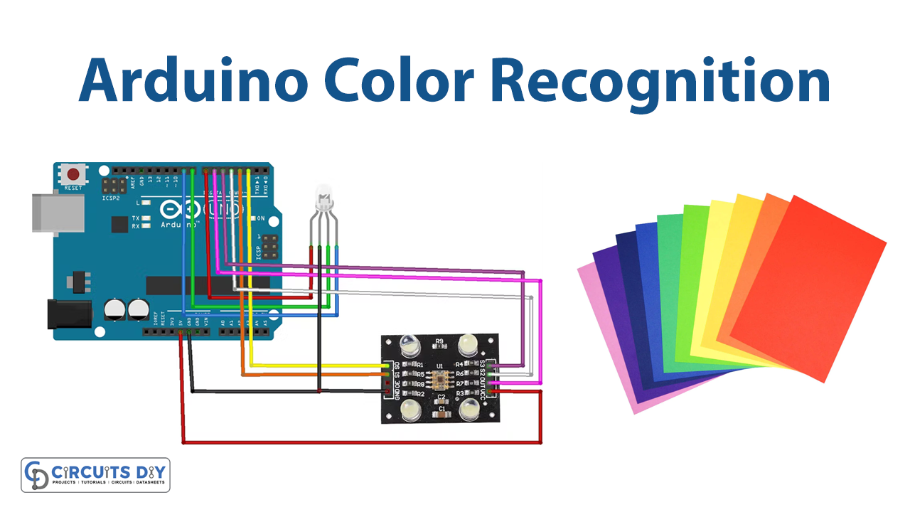
Schematic
Make connections according to the circuit diagram given below.

Wiring / Connections
| Arduino | Color sensor | RGB LED |
|---|---|---|
| 5V | VCC | |
| GND | GND | GND |
| D2 | S0 | |
| D3 | S1 | |
| D4 | S2 | |
| D5 | S3 | |
| D6 | OUT | |
| D7 | R | |
| D8 | G | |
| D9 | B |
Installing Arduino IDE
First, you need to install Arduino IDE Software from its official website Arduino. Here is a simple step-by-step guide on “How to install Arduino IDE“.
Code
Now copy the following code and upload it to Arduino IDE Software.
//Arduino pins:
#define S0 2
#define S1 3
#define S2 4
#define S3 5
#define sensorOut 6
#define redLED 7
#define greenLED 8
#define blueLED 9

//Output from the sensor:
int redFrequency = 0;
int greenFrequency = 0;
int blue Frequency = 0;

//Formatted color values:
int redColor = 0;
int greenColor = 0;
int blueColor = 0;

//Values used for calibration
int redMin;
int redMax;
int greenMin;
int greenMax;
int blueMin;
int blueMax;

int color = 0;

void setup() {
 //Declarations:
 pinMode(S0, OUTPUT);
 pinMode(S1, OUTPUT);
 pinMode(S2, OUTPUT);
 pinMode(S3, OUTPUT);
 pinMode(redLED, OUTPUT);
 pinMode(greenLED, OUTPUT);
 pinMode(blueLED, OUTPUT);
 pinMode(13, OUTPUT);
 pinMode(sensorOut, INPUT);
 // Set frequency scaling to 20%:
 digitalWrite(S0, HIGH);
 digitalWrite(S1, LOW);
 Serial.begin(9600);//begin serial communication
 calibrate();//calibrate sensor (look at serial monitor)
}

void loop() {
 readColor();//read sensor
 decideColor();//format color values
 printColor();//print values
}

void decideColor() {//format color values
 //Limit possible values:
 redColor = constrain(redColor, 0, 255);
 greenColor = constrain(greenColor, 0, 255);
 blueColor = constrain(blueColor, 0, 255);

//find the brightest color:
 int maxVal = max(redColor, blueColor);
 maxVal = max(maxVal, greenColor);
 //map new values
 redColor = map(redColor, 0, maxVal, 0, 255);
 greenColor = map(greenColor, 0, maxVal, 0, 255);
 blueColor = map(blueColor, 0, maxVal, 0, 255);
 redColor = constrain(redColor, 0, 255);
 greenColor = constrain(greenColor, 0, 255);
 blueColor = constrain(blueColor, 0, 255);

 //light led
 analogWrite(redLED, redColor);
 analogWrite(greenLED, greenColor);
 analogWrite(blueLED, blueColor);
//decide which color is present (you may need to change some values here):
 if (redColor > 250 && greenColor > 250 && blueColor > 250) {
   color = 1;//white
 }
 else if (redColor < 25 && greenColor < 25 && blueColor < 25) {
   color = 2;//black
 }
 else if (redColor > 200 &&  greenColor > 200 && blueColor < 100) {
   color = 4;//yellow
 }
 else if (redColor > 200 &&  greenColor > 25 /*&& blueColor < 100*/) {
   color = 3;//orange
 }
 else if (redColor > 200 &&  greenColor < 100 && blueColor > 200) {
   color = 5;//purple
 }
 else if (redColor > 250 && greenColor < 200 && blueColor < 200) {
   color = 6;//red
 }
 else if (redColor < 200 && greenColor > 250 && blueColor < 200) {
   color = 7;//green
 }
 else if (redColor < 200 /*&& greenColor < 200*/ && blueColor > 250) {
   color = 8;//blue
 }
 else {
   color = 0;//unknown
 }
}

void calibrate() {
 Serial.println("Calibrating...");
 Serial.println("White");//aim sensor at something white
 //set calibration vaues:

 digitalWrite(13, HIGH);
 delay(2000);
 digitalWrite(S2, LOW);
 digitalWrite(S3, LOW);
 redMin = pulseIn(sensorOut, LOW);
 delay(100);
 digitalWrite(S2, HIGH);
 digitalWrite(S3, HIGH);
 greenMin = pulseIn(sensorOut, LOW);
 delay(100);
 digitalWrite(S2, LOW);
 digitalWrite(S3, HIGH);
 blueMin = pulseIn(sensorOut, LOW);
 delay(100);
 Serial.println("next...");//aim sensor at something black
 digitalWrite(13, LOW);
 delay(2000);
 Serial.println("Black");

 //set calibration values:
 digitalWrite(13, HIGH);
 delay(2000);
 digitalWrite(S2, LOW);
 digitalWrite(S3, LOW);
 redMax = pulseIn(sensorOut, LOW);
 delay(100);
 digitalWrite(S2, HIGH);
 digitalWrite(S3, HIGH);
 greenMax = pulseIn(sensorOut, LOW);
 delay(100);
 digitalWrite(S2, LOW);
 digitalWrite(S3, HIGH);
 blueMax = pulseIn(sensorOut, LOW);
 delay(100);
 Serial.println("Done calibrating.");
 digitalWrite(13, LOW);
}

void printColor() {//print data
 Serial.print("R = ");
 Serial.print(redColor);
 Serial.print(" G = ");
 Serial.print(greenColor);
 Serial.print(" B = ");
 Serial.print(blueColor);
 Serial.print(" Color: ");
 switch (color) {
   case 1: Serial.println("WHITE"); break;
   case 2: Serial.println("BLACK"); break;
   case 3: Serial.println("ORANGE"); break;
   case 4: Serial.println("YELLOW"); break;
   case 5: Serial.println("PURPLE"); break;
   case 6: Serial.println("RED"); break;
   case 7: Serial.println("GREEN"); break;
   case 8: Serial.println("BLUE"); break;
   default: Serial.println("unknown"); break;
 }
}

void readColor() {//get data from sensor
 //red:
 digitalWrite(S2, LOW);
 digitalWrite(S3, LOW);
 redFrequency = pulseIn(sensorOut, LOW);
 redColor = map(redFrequency, redMin, redMax, 255, 0);
 delay(100);

 //green:
 digitalWrite(S2, HIGH);
 digitalWrite(S3, HIGH);
 greenFrequency = pulseIn(sensorOut, LOW);
 greenColor = map(greenFrequency, greenMin, greenMax, 255, 0);
 delay(100);

 //blue:
 digitalWrite(S2, LOW);
 digitalWrite(S3, HIGH);
 blueFrequency = pulseIn(sensorOut, LOW);
 blueColor = map(blueFrequency, blueMin, blueMax, 255, 0);
 delay(100);
}
Let’s Test It
It’s now time to put the circuit to the test. After you’ve uploaded the code, turn on the Arduino. When the sensor is prepared for usage, you must perform the initial calibration:
- Open the serial monitor
- Aim the sensor toward a 1 distance away white object.
- Wait for “next” to appear on the serial display.
- Aim the sensor in the same direction towards a dark object.
- Await the serial monitor to indicate that calibration is complete.
Now that the sensor should have been calibrated, you may utilise it:
- Simply aim it at something to activate passive detection, and the LED should change to match the observed colour.
- Open the serial monitor and wait for the sensor readings to appear for active detection.
Working Explanation
To understand the working, it is necessary to dig into the coding:
- Define the Arduino pins that are connected to the sensor. Also, define the pin of the Arduino that will provide an output value. In our case, we choose pin 6. Make integer variables redfrequency, greenfrequency, and blue frequency to store the frequencies which are 0 initially. Also, make three more variables and name the redcolor, bluecolor, and greencolor. We then define some more variables like redMin, redMax; etc. These would be the calibration values
- We have specified the input and output pins in the void setup. Set the frequency scaling to 20%: and initialize the serial monitor. Then we use the function to calibrate the sensor.
- In the void loop, we give the functions to read, format, and print the color values.
- In the void decideColor() we constrain and map the color values using constrain and map functions. This section of code is solely used to detect “active” colors.
- In the void calibration, we program to set the calibration values. Two control pins, S2 and S3 have been defined at the low logic level in order to set the red filtered photodiode. We have designated S2 and S3 as high levels to establish the green filtered photodiode. Additionally, we declared S2 at a high level and S3 at a low level to configure the blue filtered photodiode.
- In void printColor(), we print the data on a serial monitor.
- In void readColor() we get data from the sensor
Applications
- Light color temperature measurement
- RGB LED consistency control
- Medical diagnosis systems
- Color sorting devices
- Robotic applications; etc
Conclusion
We hope you have found this Arduino Color Recognition Circuit very useful. If you feel any difficulty in making it, feel free to ask anything in the comment section.