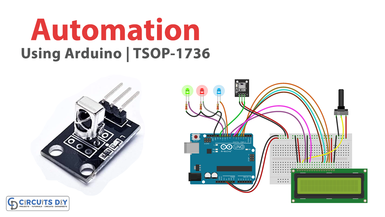
Introduction
Remote Control Automation Using TSOP 1738 Sensor And Arduino UNO microcontroller is an innovative project that brings automation and remote control capabilities to electrical appliances. This project utilizes the power of IR technology and an Arduino microcontroller to enable users to control different electrical devices using a remote control. The TSOP 1738 sensor acts as the interface between the remote control and the Arduino microcontroller, converting IR signals from the remote control into electrical signals that the microcontroller can interpret and act upon.
This project has vast applications in home automation and industrial control systems, providing a convenient and efficient way of managing appliances and devices from a distance. With its ease of implementation, the Remote Control Automation Using TSOP 1738 Sensor And Arduino UNO microcontroller is an excellent starting point for hobbyists, students, and professionals looking to explore the world of automation and control systems.
Hardware Components
You will require the following hardware for Automation Using TSOP-1738.
| Components | Value | Qty |
|---|---|---|
| Arduino UNO | – | 1 |
| TSOP Sensor Module | TSOP-1738 | 1 |
| LCD Display | 16X2 | 1 |
| Potentiometer | 10kΩ | 1 |
| LEDs | Different Colors | 1 |
| Resistor | 220Ω | 1 |
| Breadboard | – | 1 |
| Jumper Wires | – | 1 |
Code Explanation
- Importing libraries
#include <IRremote.h>
#include "LiquidCrystal.h"
The code starts by including two libraries: IRremote.h for receiving IR signals and LiquidCrystal.h for controlling the LCD screen.
- Initializing variables
int val1=0;
int val2=0;
int val3=0;
int val4=0;
int Data ;
The code initializes four variables (val1, val2, val3, val4) to store the status of each LED and a variable (Data) to store the decoded IR signal.
- Setting pin modes
LiquidCrystal lcd(8,7,6,5,4,3);
int RECV_PIN = 12;
pinMode(11,OUTPUT);
pinMode(10,OUTPUT);
pinMode(9,OUTPUT);
The code sets up the pin modes for the LCD screen and the LEDs. The LCD screen is connected to pins 8, 7, 6, 5, 4, and 3, and the IR receiver is connected to pin 12.
- Initializing the LCD screen
lcd.begin(16,2);
lcd.setCursor(0,0);
lcd.print(" Remote Control    ");
lcd.setCursor(0,1);
lcd.print("   Automation   ");
delay(5000);
lcd.clear();
The code initializes the LCD screen by calling the begin() function with the dimensions of the screen (16×2). It then displays a message for 5 seconds and clears the screen.
- Setting up the IR receiver
IRrecv irrecv(RECV_PIN);
decode_results results;
Serial.println("Enabling IRin");
irrecv.enableIRIn();
Serial.println("Enabled IRin");
The code creates an instance of the IRrecv class and passes the pin number to the constructor. It then creates a decode_results object to store the decoded IR signal. The code enables the IR receiver and prints some messages to the serial monitor for debugging purposes.
- Receiving and decoding IR signals
if (irrecv.decode(&results)) {
    Data = results.value, HEX;
    irrecv.resume();
    // check value of Data and toggle corresponding LED
}
The loop() function waits for an IR signal using the irrecv.decode() function. If a signal is received, the function decodes the signal and stores it in the Data variable. The code then checks the value of Data and turns on or off the appropriate LED depending on the value. The code also updates the LCD screen to display the current status of the LEDs.
- Toggling LEDs and updating LCD screen
if(Data==18615) {
    val1=digitalRead(11);
    if(val1==0) {
        digitalWrite(11,HIGH);
        val1=1;
        lcd.setCursor(7,0);
        lcd.print("Led 1 ON     ");
        delay(500);
    }
    else {
        digitalWrite(11,LOW);
        val1=0;
        lcd.setCursor(7,0);
        lcd.print("Led 1 OFF     ");
        delay(100);
    }
}
// similar code for val2 and val3
The code uses a variable to store the last status of each LED, so it can toggle the LED’s state with each IR signal received. It checks the value of Data and toggles the appropriate LED using digitalRead() and digitalWrite() functions. It also updates the LCD screen to display the current status of the LEDs using the lcd.setCursor() and lcd.print() functions.
Schematic
Make connections according to the circuit diagram given below.

Installing Arduino IDE
First, you need to install Arduino IDE Software from its official website Arduino. Here is a simple step-by-step guide on “How to install Arduino IDE“.
Installing Libraries
Before you start uploading a code, download and unzip the following libraries at /Progam Files(x86)/Arduino/Libraries (default), in order to use the sensor with the Arduino board. Here is a simple step-by-step guide on “How to Add Libraries in Arduino IDE“.
Code
Now copy the following code and upload it to Arduino IDE Software.
#include <IRremote.h>
#include "LiquidCrystal.h"

LiquidCrystal lcd(8,7,6,5,4,3);
int val1=0; // Inializing the variable for storing the last status of Relay_pins
int val2=0;
int val3=0;
int val4=0;
int RECV_PIN = 12;
int Data ;
IRrecv irrecv(RECV_PIN);
decode_results results;
void setup()
{
 Serial.begin(9600);
 lcd.begin(16,2);

 // In case the interrupt driver crashes on setup, give a clue
 // to the user what's going on.
 Serial.println("Enabling IRin");
 irrecv.enableIRIn(); // Start the receiver
 Serial.println("Enabled IRin");
 pinMode(11,OUTPUT); // LED 1
 pinMode(10,OUTPUT); // LED 2
 pinMode(9,OUTPUT);  // LED 3
 lcd.setCursor(0,0);
 lcd.print(" Remote Control    ");
 lcd.setCursor(0,1);
 lcd.print("   Automation   ");
 delay(5000);
 lcd.clear();

}
void loop() {
 if (irrecv.decode(&results))
 {
  Data = results.value, HEX ;
  Serial.println(Data);
  lcd.setCursor(0,0);
  lcd.print(Data);
  irrecv.resume(); // Receive the next value
  if(Data==18615)
  {
   val1=digitalRead(11);
   if(val1==0)
   {
    digitalWrite(11,HIGH);
    val1=1;
    lcd.setCursor(7,0);
    lcd.print("Led 1 ON     ");
    delay(500);
   }
   else
   {
   digitalWrite(11,LOW);
   val1=0;
    lcd.setCursor(7,0);
    lcd.print("Led 1 OFF     ");
   delay(100);
   }
  }
  if(Data==22695)
  {
   val2=digitalRead(10);
   if(val2==0)
   {
    digitalWrite(10,HIGH);
    val2=1;
    lcd.setCursor(0,1);
    lcd.print("L 2 ON ");
    delay(500);
   }
   else
   {
   digitalWrite(10,LOW);
   val2=0;
    lcd.setCursor(0,1);
    lcd.print("L 2 OFF");
   delay(100);
   }
  }
  if(Data==2295)
  {
   val3=digitalRead(9);
   if(val3==0)
   {
    digitalWrite(9,HIGH);
    val3=1;
    lcd.setCursor(7,1);
    lcd.print("L 3 ON ");
    delay(500);
   }
   else
   {
   digitalWrite(9,LOW);
   val3=0;
    lcd.setCursor(7,1);
    lcd.print("L 3 OF");
   delay(100);
   }
  }
 }
 delay(100);
}
Working Explanation
The first part of the code includes the required libraries for IR remote and LiquidCrystal display. The IRremote.h library provides the necessary functions to decode the IR signals received by the IR receiver connected to pin 12. The LiquidCrystal.h library is used to control the 16×2 LCD display connected to the Arduino pins 8 to 3.
The setup() function initializes the serial communication with a baud rate of 9600, enables the IR receiver, and sets the pins 9, 10, and 11 as output pins for controlling the LEDs. The LCD display shows a welcome message for 5 seconds and then gets cleared. The loop() function continuously listens for IR signals using the irrecv.decode() function. When a signal is received, the function decodes the signal and stores the value in the variable “Data”. The decoded value is then printed on the LCD display using lcd.print() function.
The code checks the decoded value to determine which button on the IR remote is pressed. If the button matches a particular value, the code reads the status of the corresponding LED (using digitalRead()) and toggles its state (using digitalWrite()). The code also updates the value of the corresponding variable (val1, val2, or val3) to reflect the current state of the LED. The LCD display is updated to show the current status of the LEDs (ON/OFF) whenever a button is pressed. The delay() function is used to control the speed of the LED toggling and the LCD display update. The irrecv.resume() function is used to receive the next IR signal.
Applications
- Home automation
- Industrial automation – controlling industrial equipment remotely.
- Security systems – remote control of locks, cameras, and alarms.
- Robotics
- Agriculture
- Automotive
- Healthcare
Related posts:
 Interfacing Character LCD Modules 0802 / 1602 / 2002 / 2004 with Arduino
 Electromagnetic Lock - Arduino Tutorial
 DHT11/DHT22 Temperature Humidity Sensor - Arduino Tutorial
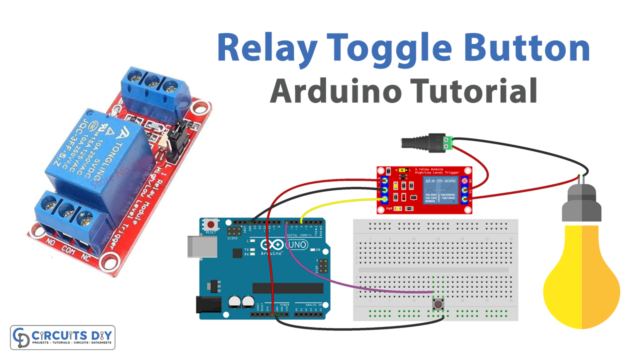 Button Toggle Relay - Arduino Tutorial
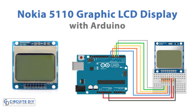 Interface Nokia 5110 Graphic LCD Display with Arduino
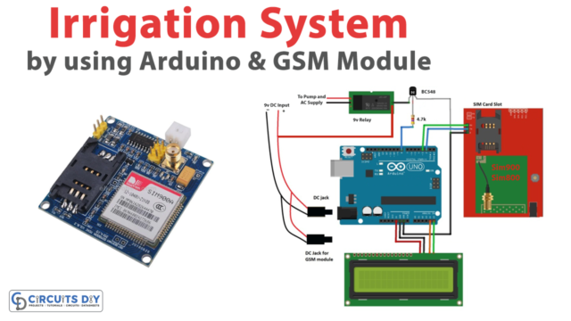 Irrigation System Circuit using GSM and Arduino