Introduction
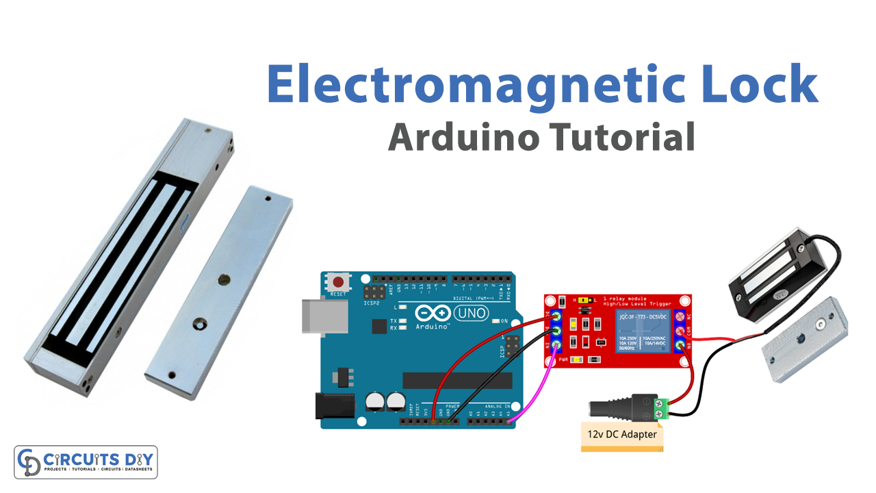
A 5V SPDT (Single Pole Double Throw) relay-controlled Electromagnetic door lock is an electronic device that allows you to control the locking and unlocking of a door remotely. This system uses an Arduino UNO microcontroller, which acts as the brain of the lock, and a relay, which is responsible for switching the power supply to the electromagnetic lock. The relay is controlled by the Arduino UNO microcontroller, which can be programmed to lock and unlock the door at specific times or in response to certain events.
A magnetic reed switch is a type of electrical switch that uses a magnetic field to control its operation. It consists of a reed element, typically made of a ferromagnetic material, and a fixed magnetic field source. When the magnetic field source is brought close to the reed element, it becomes magnetized and attracts the reed, causing it to move and close an electrical circuit. When the magnetic field is removed, the reed returns to its original position and opens the circuit. Magnetic reed switches are commonly used in various applications such as security systems, door sensors, and automation systems.
Hardware Components
You will require the following hardware for Electromagnetic Lock with Arduino.
| S.no | Component | Value | Qty |
|---|---|---|---|
| 1. | Arduino UNO | – | 1 |
| 2. | USB Cable Type A to B | – | 1 |
| 3. | Electromagnetic Lock | – | 1 |
| 4. | Relay | – | 1 |
| 5. | Power Adapter | 12V | 1 |
| 6. | DC Power Jack | – | 1 |
| 7. | Power Adapter for Arduino | 9V | 1 |
Electromagnetic Lock with Arduino
- Constants:
const int RELAY_PIN = A5;
This line defines a constant integer named RELAY_PIN with a value of A5. A5 is an analog pin on the Arduino board, which will be used to control the relay.
- Setup Function:
void setup() {
  pinMode(RELAY_PIN, OUTPUT);
}
The setup function is called once when the Arduino board is powered on or reset. In this function, we set the mode of RELAY_PIN as OUTPUT using the pinMode function. This function is used to set the specified pin as an output or input.
- Loop Function:
void loop() {
  digitalWrite(RELAY_PIN, HIGH);
  delay(5000);
  digitalWrite(RELAY_PIN, LOW);
  delay(5000);
}
The loop function is called repeatedly and forever after the setup function is executed. In this function, we are using the digitalWrite function to write HIGH or LOW to the specified pin. Writing HIGH to the RELAY_PIN means that the relay is in the “ON” state, which locks the door. Writing LOW to the RELAY_PIN means that the relay is in the “OFF” state, which unlocks the door.
Schematic
Make connections according to the circuit diagram given below.
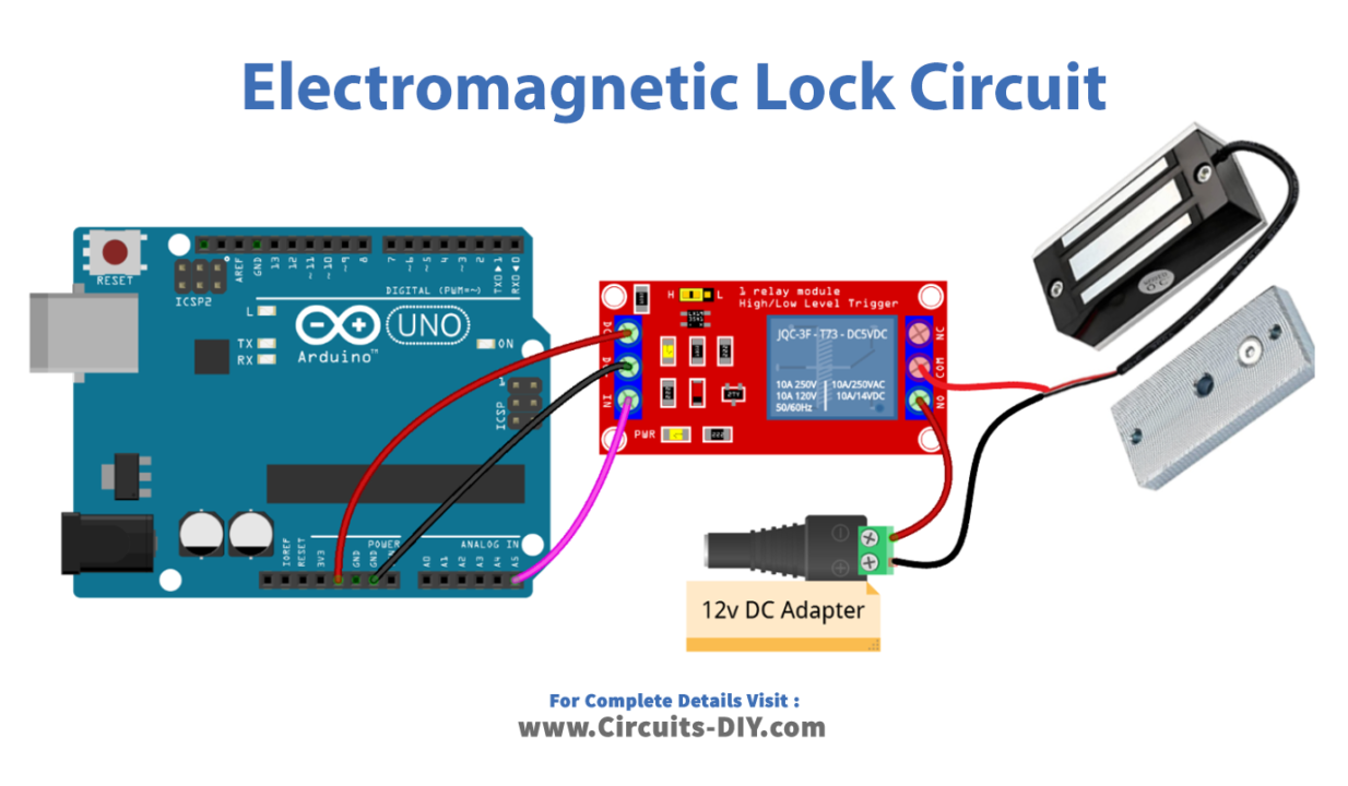
Wiring / Connections
| Arduino | Relay |
|---|---|
| 5V | VCC |
| GND | GND |
| A5 | INP |
Installing Arduino IDE
First, you need to install Arduino IDE Software from its official website Arduino. Here is a simple step-by-step guide on “How to install Arduino IDE“.
Code
Now copy the following code and upload it to Arduino IDE Software.
// constants won't change
const int RELAY_PIN = A5;  // the Arduino pin, which connects to the IN pin of relay

// the setup function runs once when you press reset or power the board
void setup() {
  // initialize digital pin A5 as an output.
  pinMode(RELAY_PIN, OUTPUT);
}

// the loop function runs over and over again forever
void loop() {
  digitalWrite(RELAY_PIN, HIGH); // lock the door
  delay(5000);
  digitalWrite(RELAY_PIN, LOW);  // unlock the door
  delay(5000);
}
Working Explanation
The setup() function is executed once when you power on the Arduino or press the reset button. It initializes the digital pin A5 as an output, which is connected to the IN pin of the relay. This pin will be used to control the relay and lock/unlock the door.
The loop() function runs repeatedly and is responsible for controlling the relay and locking and unlocking the door. In this code, the relay is locked by setting the digital pin A5 to HIGH, which activates the relay and locks the door. This state is maintained for 5 seconds using the delay() function. Then the relay is unlocked by setting the digital pin A5 to LOW, which deactivates the relay and unlocks the door. Again, this state is maintained for 5 seconds.
Applications
- Access control systems
- Smart homes
- Office security systems
- Automated gates and doors
- Automatic door unlocking systems
- Surveillance systems
Conclusion.
We hope you have found this Electromagnetic Lock Circuit very useful. If you feel any difficulty in making it feel free to ask anything in the comment section.