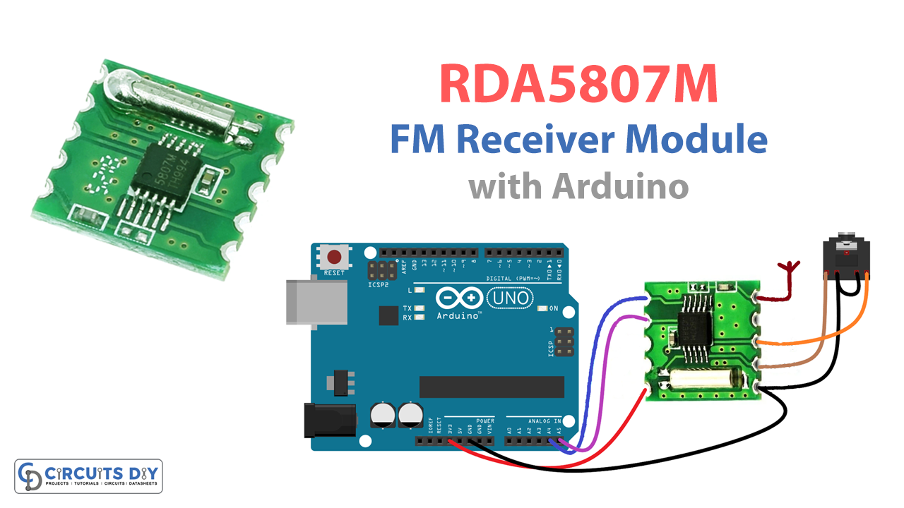
Long ago we were all depending on local FM radios, to get the latest news and songs. Slowly these radios are losing popularity. But in emergencies when the internet is down, radios place an important role to transmit information. Here if we make FM or radio receivers by using radio tuner components.
As we know, these components require a lot of effort to build an accurate radio receiver. Radio signals are always present in the air and all we need is an FM receiver circuit, to catch those radio signals and transfer them to audio signals. Here we design a simple and easy-to-build FM radio receiver module, that is used to receive FM signals by using RDA5807M and Arduino microcontroller board. You can tune and control this module by using a microcontroller I2C line.
Hardware Required
| S.no | Component | Value | Qty |
|---|---|---|---|
| 1. | Arduino UNO | – | 1 |
| 2. | USB Cable Type A to B | – | 1 |
| 3. | Jumper Wires | – | – |
| 4. | RDA Chip | RDA5807M | 1 |
RDA5807M Module Pin Configuration
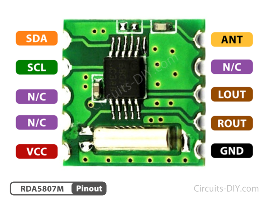
The RDA5807M is a simple stereo radio chip, that supports worldwide FM bands from 50MHz to 115MHz. It has a fully integrated synthesizer, intermediate frequency (IF) selectivity, RDS/RBDS, and an MPX decoder. It has features, like autonomous search tuning, direct auto gain control (AGC), and digital adaptive noise cancellation. This chip has a powerful low-IF digital audio processor, which means that you can directly listen to the audio via headphones. If you wish to connect it to bigger speakers, then you might need an audio amplifier circuit.
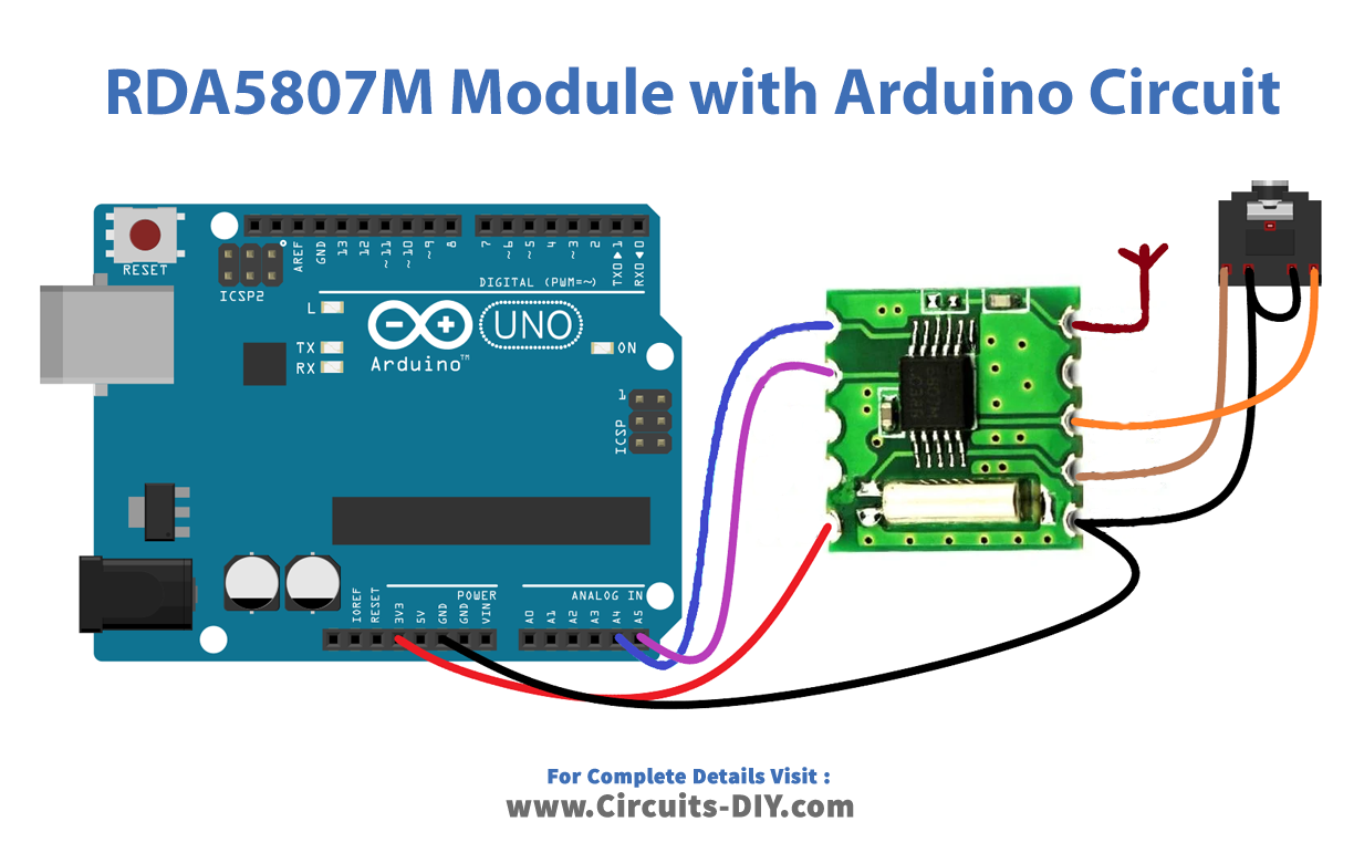
Arduino RDA5807M Interfacing
Working Explanation
RDA5807M module has few external connecting terminals, it can be easily interfaced with Arduino. The module works on a power supply of 1.8 – 3.3V. When coming to rest and the control interface is selected, the module resets itself when VIO is powered up. And also supports soft reset by the trigger of bit1 from 0 to 1 of the 02H address. The module uses I2C communication, to communicate with the MCU. And the interface begins with a start condition, a command byte, and data bytes. The RDA5807 has 13 16-bit registers, each performing a particular function. The register addresses start with 00H, which is allotted to chip ID, and end with 0FH. In all 13 registers, some bits are reserved while some are R/W. Each register performs tasks, like varying volume, changing channels, etc. Which is depending upon the bits assigned to them. Here FM receiver module’s Vcc pin is connected to the 3.3V power pin of Arduino, SDA (Serial Data Line) is connected to the A4 (SDA) and SCL (Serial Clock Line) is connected to the A5 (SCL) pin. 1-foot single-strand wire can react as Antenna. Rout (Right audio out), Lout (Left audio out) of RDA5807M module is connected with a 3.5mm audio jack female connector, then common GND is connected to Arduino GND pin. When the module is powered up, our code resets the RDA5807-M IC and sets it to a channel of the user desired (Note: this frequency is taken as the base frequency upon which the frequency will be incremented).
After wiring use the following RDA 5807M Arduino Library created by Matthias Hertel (http://mathertel.blogspot.in).
Arduino RDA5807M Code
#include <Arduino.h>
#include <Wire.h>
#include <radio.h>
#include <RDA5807M.h>
#define FIX_BAND     RADIO_BAND_FM    //Radio Band -FM
#define FIX_STATION  10050            //Station Tuned = 100.50 MHz.
#define FIX_VOLUME   5               //Audio Volume Level 5.

RDA5807M radio;

void setup() {

  Serial.begin(57600);
  Serial.println("FM Radio");
  delay(200);
  radio.init();
  radio.debugEnable();
  radio.setBandFrequency(FIX_BAND, FIX_STATION);
  radio.setVolume(FIX_VOLUME);
  radio.setMono(false);
  radio.setMute(false);
}

void loop() {
  char s[12];
  radio.formatFrequency(s, sizeof(s));
  Serial.print("Station:");
  Serial.println(s);
  Serial.print("Radio:");
  radio.debugRadioInfo();
  Serial.print("Audio:");
  radio.debugAudioInfo();
  delay(3000);
}
Applications
- Smartphones
- Satellite Communication
- Modems
Related posts:
 Distance Meter with OLED & Arduino
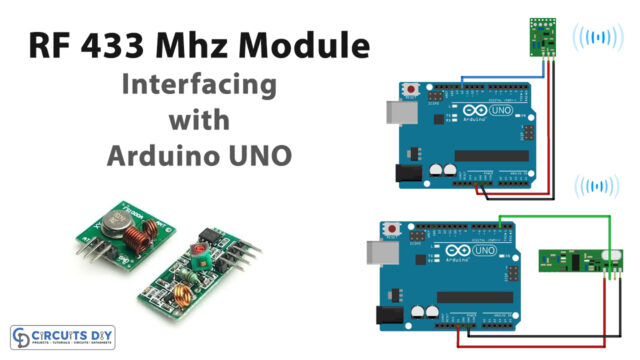 How to Interface RF Transmitter/Receiver Module With Arduino UNO
 How to generate Super Mario Theme Song by using Arduino Microcontroller
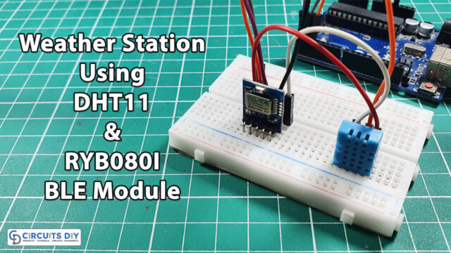 Weather Station using RYB080I Bluetooth Low Energy (BLE) Module with Arduino
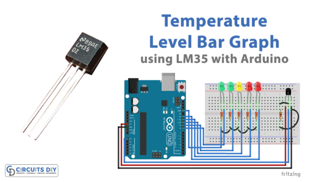 Temperature Level Bar Graph using LM35 with Arduino
 LED Pattern with Push button using Arduino