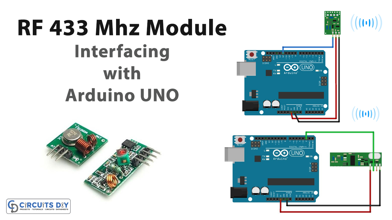
Introduction
To transmit and receive the data in any device, the RF modules are used essentially. For wireless devices, these modules can be used in the pair. Hence, the transmitter transmits the data. While receive takes that data. The RF modules usually can reach three-meter. However, through the proper antennas and supplies, it may obtain the data within 100 meters. But, practically, it can collect data within the vicinity of 30 or 35 meters. So, the projects that require communication within 35 meters can use the RF modules. Therefore, In this tutorial, we are going to interface ” 433MHz Transmitter/Receiver Module with Arduino UNO”
Working of RF Module
RF modules work with the collaboration of microcontrollers. Since it uses the amplitude shift keying. Therefore, it’s easy to interface the module with any microcontroller. However, as the distance, gets increases, it receives the data with noise.
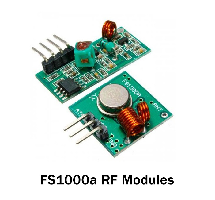
Specifications about RF Module
- The module provides wireless transmission and receiving.
- The transmitter voltage range is 3 to 12V
- The receiver voltage range is 5Volts
- The receiver draws the current of 5.5mA
- The operating frequency of the nodule is 433MHz
- The speed to transmit data is 10 kbps
- The module is inexpensive and affordable
Hardware Required
| S.no | Component | Value | Qty |
|---|---|---|---|
| 1. | Arduino | UNO | 1 |
| 2. | USB Cable Type A to B | – | 1 |
| 3. | Jumper Wires | – | – |
| 4. | Transmitter/Receiver Module | 433MHz | 1 |
Transmitter Circuit
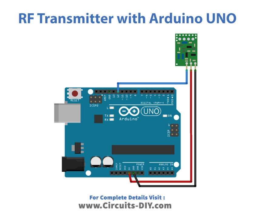
Connection Table
| Arduino | 433MHz Transmitter Module |
|---|---|
| D12 | Data |
| 5V | Vcc |
| GND | GND |
Arduino Code for Transmitter
// Circuits DIY
// For Complete Details Visit -> https://circuits-diy.com

#include <RH_ASK.h>
#include <SPI.h> // Not actually used but needed to compile

RH_ASK driver;

void setup()
{
    Serial.begin(9600);	  // Debugging only
    if (!driver.init())
         Serial.println("init failed");
}

void loop()
{
    const char *msg = "Hello World!";
    driver.send((uint8_t *)msg, strlen(msg));
    driver.waitPacketSent();
    delay(1000);
}
Receiver Circuit
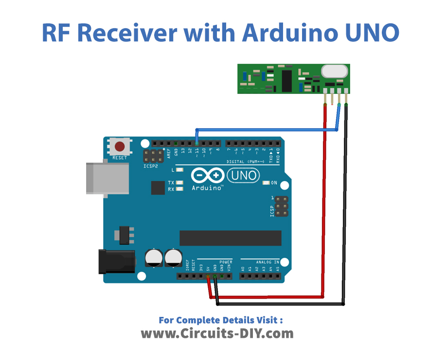
Connections Table
| Arduino | 433MHz Receiver Module |
|---|---|
| D11 | Data |
| 5V | Vcc |
| GND | GND |
Arduino Code for Receiver
// Circuits DIY
// For Complete Details Visit -> https://circuits-diy.com

#include <RH_ASK.h>
#include <SPI.h> // Not actualy used but needed to compile

RH_ASK driver;

void setup()
{
    Serial.begin(9600);	// Debugging only
    if (!driver.init())
         Serial.println("init failed");
}

void loop()
{
    uint8_t buf[12];
    uint8_t buflen = sizeof(buf);
    if (driver.recv(buf, &buflen)) // Non-blocking
    {
      int i;
      // Message with a good checksum received, dump it.
      Serial.print("Message: ");
      Serial.println((char*)buf);
    }
}
Working Explanation
Assemble the RF 433MHz Transmitter/Receiver Module With Arduino Uno according to the diagram above. Upload the above-mentioned code. Open the serial monitor. When the transmitter sends the message ‘Hello world’, it will be shown on the Serial monitor.
Code Explanation
- Firstly, download the radio Head ASK library for the module. You can download the library from:
https://github.com/PaulStoffregen/RadioHead/blob/master/RH_ASK.h
For the transmitter Side
- First, we have included the radio Head ASK for the module and SPI library for the external communication with the module. Then, we have created the object driver
- In the void setup, we have initialized the Serial monitor by serial. begin. Also, we have initialized the driver object by init( ).
- In the void loop, we have written the message ‘Hello world’ and stored it in the variable msg. Then we have sent the message using the send ( ) function. The delay is given to adjust the time after which another message will be sent.
For The Reciever Side
- We first have included the radio Head ASK for the module and SPI library for the external communication with the module. Then, we have created the object driver
- In the void setup, we have initialized the Serial monitor by serial. begin. Also, we have initialized the driver object by init( ).
- In the void loop, we have set the buffer to match the size of the message we are going to receive. Then, there is a program to check if the message is valid. The message is then printed on the Serial monitor.
Application and Uses
- It is used for wireless communication.
- In the car security system.
- Can be utilized in the home automation system
- Also, in the short distance communication devices