Introduction
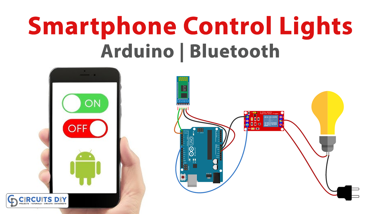
Smartphone-controlled home appliances using an Arduino Uno and an Android app with an HC-05 Bluetooth module is a fascinating DIY project that merges technology and home automation. This project allows you to control your home appliances from your smartphone, bringing convenience and ease to your daily life.
By leveraging the capabilities of the Arduino Uno microcontroller board and the HC-05 Bluetooth module, you can create a wireless communication system that enables you to turn on and off your lights, fans, or other devices with just a few taps on your smartphone screen. With this project, you can step into the world of smart homes and experience the power of technology at your fingertips.
Hardware Components
You will require the following hardware for Smartphone Control Light.
| Components | Value | Qty |
|---|---|---|
| Arduino UNO | – | 1 |
| Bluetooth Module | HC-05 | 1 |
| Single Channel Relay | – | 1 |
| Bulb | – | 1 |
| Breadboard | – | 1 |
| Jumper Wires | – | 1 |
Useful Steps
- Connect the HC-05 Bluetooth module to the Arduino UNO as follows:
- VCC pin to 5V pin on the Arduino UNO
- GND pin to GND pin on the Arduino UNO
- TXD pin to pin 10 on the Arduino UNO
- RXD pin to pin 11 on the Arduino UNO
- Connect the 4 channel SPDT relay module to the Arduino UNO as follows:
- VCC pin to 5V pin on the Arduino UNO
- GND pin to GND pin on the Arduino UNO
- IN1, IN2, IN3, and IN4 pins to pins 2, 3, 4, and 5 on the Arduino UNO
- Connect the 3 AC light bulbs to the SPDT relay module as follows:
- One wire from the first AC light bulb to the COM pin on the first relay module
- Another wire from the first AC light bulb to the NO or NC pin on the first relay module (depending on the desired operation)
- Repeat the above steps for the second and third AC light bulbs, connecting them to the second and third relay modules respectively.
- Create an MIT App Inventor app as follows:
- Create a new project and design the app interface as desired.
- Add a Bluetooth Client component to the app.
- Add three Button components to the app and set their texts to “ON1”, “ON2”, and “ON3”.
- Add another three Button components to the app and set their texts to “OFF1”, “OFF2”, and “OFF3”.
- Add three Label components to the app and set their texts to “Status1: OFF”, “Status2: OFF”, and “Status3: OFF”.
- Set the properties of the Bluetooth Client component to connect to the HC-05 Bluetooth module.
- Include the SoftwareSerial library:
#include <SoftwareSerial.h>6. Create a SoftwareSerial object for Bluetooth communication, specifying the RX and TX pins:
SoftwareSerial BTSerial(10, 11); // RX, TX7. Initialize the serial communication for debugging with the computer:
Serial.begin(9600);8. Initialize the Bluetooth serial communication:
BTSerial.begin(9600);9. Set the output pins for the light bulbs:
pinMode(2, OUTPUT);
pinMode(3, OUTPUT);
pinMode(4, OUTPUT);
10. Enter the main loop:
void loop() {11. Check if there is any data available from the Bluetooth device:
if (BTSerial.available()) {12. If data is available, read a character from the Bluetooth serial port:
char cmd = BTSerial.read();13. Check the value of the received character and perform an action accordingly:
if (cmd == '1') {
  digitalWrite(2, HIGH);
  Serial.println("AC Light bulb 1 turned ON");
  BTSerial.println("ON1");
} else if (cmd == '2') {
  digitalWrite(3, HIGH);
  Serial.println("AC Light bulb 2 turned ON");
  BTSerial.println("ON2");
} else if (cmd == '3') {
  digitalWrite(4, HIGH);
  Serial.println("AC Light bulb 3 turned ON");
  BTSerial.println("ON3");
} else if (cmd == '0') {
  digitalWrite(2, LOW);
  digitalWrite(3, LOW);
  digitalWrite(4, LOW);
  Serial.println("All AC Light bulbs turned OFF");
  BTSerial.println("OFF");
}
14. Repeat the loop:
}15. Modify the MIT App Inventor app as follows: Add an event handler to the “ON1” button to send the command “1” to the Arduino UNO when clicked. Add an event handler to the “OFF1” button to send the command “0” to turn off the first AC light bulb when clicked.
16. Add event handlers to the “ON2”, “OFF2”, “ON3”, and “OFF3” buttons to send the commands “2”, “0”, “3”, and “0” respectively.
17. Add an event handler to the Bluetooth Client component to receive data from the Arduino UNO.
18. Add an event handler to update the “Status1”, “Status2”, and “Status3” labels based on the received data.
19. Compile the MIT App Inventor app and install it on your smartphone.
20. Connect the Arduino UNO to a power source and turn on the AC light bulbs.
Schematic
Make connections according to the circuit diagram given below.
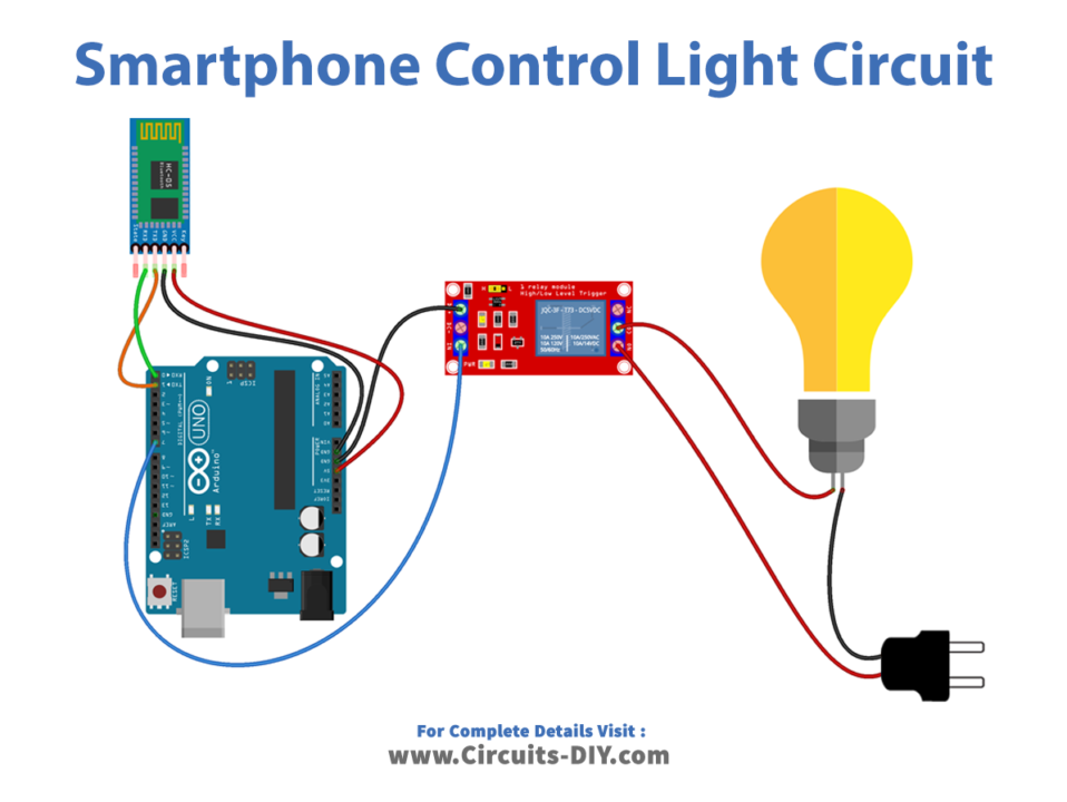
Wiring / Connections
| Arduino | HC-05 Bluetooth | Single Channel Relay |
|---|---|---|
| 5V | 5V | |
| GND | GND | GND |
| D1 | TX | |
| D0 | RX | |
| D7 | INP |
Installing Arduino IDE
First, you need to install Arduino IDE Software from its official website Arduino. Here is a simple step-by-step guide on “How to install Arduino IDE“.
Installing Libraries
Before you start uploading a code, download and unzip the following libraries at /Program Files(x86)/Arduino/Libraries (default), in order to use the sensor with the Arduino board. Here is a simple step-by-step guide on “How to Add Libraries in Arduino IDE“.
Code
Now copy the following code and upload it to Arduino IDE Software.
#include <SoftwareSerial.h>

SoftwareSerial BTSerial(10, 11); // RX, TX
void setup() {
  // Initialize the serial communication for debugging with the computer:
  Serial.begin(9600);
  // Initialize the Bluetooth serial communication:
  BTSerial.begin(9600);
  // Set the output pins for the light bulbs:
  pinMode(2, OUTPUT);
  pinMode(3, OUTPUT);
  pinMode(4, OUTPUT);
  pinMode(5, OUTPUT); // This pin is not used in the code.
}
void loop() {
  // Check if there is any data available from the Bluetooth device:
  if (BTSerial.available()) {
    // If data is available, read a character from the Bluetooth serial port:
    char cmd = BTSerial.read();
    // Check the value of the received character and perform an action accordingly:
    if (cmd == '1') {
      digitalWrite(2, HIGH);
      Serial.println("AC Light bulb 1 turned ON");
      BTSerial.println("ON1");
    } else if (cmd == '2') {
      digitalWrite(3, HIGH);
      Serial.println("AC Light bulb 2 turned ON");
      BTSerial.println("ON2");
    } else if (cmd == '3') {
      digitalWrite(4, HIGH);
      Serial.println("AC Light bulb 3 turned ON");
      BTSerial.println("ON3");
    } else if (cmd == '0') {
      digitalWrite(2, LOW);
      digitalWrite(3, LOW);
      digitalWrite(4, LOW);
      Serial.println("All AC Light bulbs turned OFF");
      BTSerial.println("OFF");
}
}
Working Explanation
In the loop function, the code checks if there is any data available from the Bluetooth device using the BTSerial.available() function. If data is available, it reads a character from the Bluetooth serial port using the BTSerial.read() function and checks the value of the received character. Depending on the value, it turns on or off one or all of the light bulbs and sends a message back to the Bluetooth device using the BTSerial.println() function to confirm the action.
If the received character is ‘1’, it turns on the first light bulb and sends a message “ON1” back to the Bluetooth device. If the received character is ‘2’, it turns on the second light bulb and sends a message “ON2” back to the Bluetooth device. If the received character is ‘3’, it turns on the third light bulb and sends a message “ON3” back to the Bluetooth device. If the received character is ‘0’, it turns off all the light bulbs and sends a message “OFF” back to the Bluetooth device.
Applications
- Home automation
- Energy efficiency
- Security
- Accessibility
- Convenience