Introduction
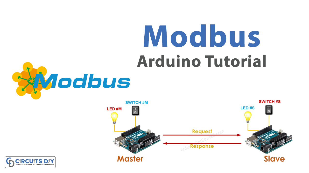
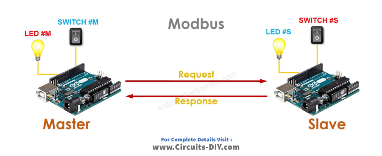
Interfacing two Arduino UNO microcontrollers with one another using the Modbus communication protocol is a fascinating project that allows you to control an LED light remotely. This project involves setting up a serial connection between two Arduinos and configuring them to communicate using the Modbus protocol. By assigning unique Modbus addresses to each Arduino and writing the appropriate code, you can send and receive messages between the Arduinos to switch the LED on and off. This project is a great way to explore the world of microcontroller communication and learn more about the Modbus protocol, which is widely used in industrial applications.
Modbus is a communication protocol used in industrial automation systems to connect and exchange data between various devices such as sensors, programmable logic controllers (PLCs), and other automation equipment. Modbus uses a master-slave architecture, where the master device initiates the communication by sending requests to the slave devices. The slave devices respond to these requests with data or status information. Modbus supports various communication media such as serial communication (RS-232/485) and Ethernet.
Hardware Components
You will require the following hardware for Interfacing Arduino – Modbus with Arduino.
| S.no | Component | Value | Qty |
|---|---|---|---|
| 1. | Arduino UNO | – | 2 |
| 2. | USB Cable Type A to B | – | 2 |
| 3. | Switch | – | 2 |
| 4. | LED | – | 2 |
Modbus with Arduino UNO
- Connect the two Arduino UNO microcontrollers using a serial cable. One microcontroller will act as the master, and the other microcontroller will act as the slave.
- On the master microcontroller, define the Modbus communication protocol by including the Modbus library and creating a Modbus object. Here’s an example:
#include <ModbusMaster.h>
ModbusMaster node;
- Define the LED and push switch pins for the master microcontroller. Here’s an example:
#define LED_PIN 7
#define SWITCH_PIN 2
- In the setup() function of the master microcontroller, initialize the serial communication, the Modbus communication protocol, and set the slave ID. Here’s an example:
void setup() {
  Serial.begin(9600);
  pinMode(LED_PIN, OUTPUT);
  pinMode(SWITCH_PIN, INPUT_PULLUP);
  node.begin(1, Serial); // Set the slave ID to 1
}
- In the loop() function of the master microcontroller, read the state of the push switch and switch ON/OFF the LED accordingly. Then, use the Modbus communication protocol to write the status of the LED to the slave microcontroller. Here’s an example:
void loop() {
  int switchState = digitalRead(SWITCH_PIN);
  digitalWrite(LED_PIN, switchState);
  node.writeSingleCoil(0, switchState); // Write the status of the LED to Modbus address 0 of the slave microcontroller
  delay(100);
}
- On the slave microcontroller, define the Modbus communication protocol by including the Modbus library and creating a Modbus object. Here’s an example:
#include <ModbusSlave.h>
ModbusSlave node;
- Define the LED pin for the slave microcontroller. Here’s an example:
#define LED_PIN 7
- In the setup() function of the slave microcontroller, initialize the serial communication, the Modbus communication protocol, and set the slave ID. Here’s an example:
void setup() {
  Serial.begin(9600);
  pinMode(LED_PIN, OUTPUT);
  node.begin(1, Serial); // Set the slave ID to 1
}
- In the loop() function of the slave microcontroller, use the Modbus communication protocol to read the status of the LED from the master microcontroller and switch ON/OFF the LED accordingly. Here’s an example:
void loop() {
  node.update();
  if (node.getCoil(0) == HIGH) {
    digitalWrite(LED_PIN, HIGH);
  } else {
    digitalWrite(LED_PIN, LOW);
  }
}
Schematic
Make connections according to the circuit diagram given below.
Installing Arduino IDE
First, you need to install Arduino IDE Software from its official website Arduino. Here is a simple step-by-step guide on “How to install Arduino IDE“.
Installing Libraries
Before you start uploading a code, download and unzip the following libraries at /Progam Files(x86)/Arduino/Libraries (default), in order to use the sensor with the Arduino board. Here is a simple step-by-step guide on “How to Add Libraries in Arduino IDE“.
Master Code
Now copy the following code and upload it to Arduino IDE Software.
#include <ModbusMaster.h>
ModbusMaster node;
#define LED_PIN 7
#define SWITCH_PIN 2
void setup() {
  Serial.begin(9600);
  pinMode(LED_PIN, OUTPUT);
  pinMode(SWITCH_PIN, INPUT_PULLUP);
  node.begin(1, Serial); // Set the slave ID to 1
}
void loop() {
  int switchState = digitalRead(SWITCH_PIN);
  digitalWrite(LED_PIN, switchState);
  node.writeSingleCoil(0, switchState); // Write the status of the LED to Modbus address 0 of the slave microcontroller
  delay(100);
}
Slave Code
Now copy the following code and upload it to Arduino IDE Software.
#include <ModbusSlave.h>
ModbusSlave node;
#define LED_PIN 7
void setup() {
  Serial.begin(9600);
  pinMode(LED_PIN, OUTPUT);
  node.begin(1, Serial); // Set the slave ID to 1
}
void loop() {
  node.update();
  if (node.getCoil(0) == HIGH) {
    digitalWrite(LED_PIN, HIGH);
  } else {
    digitalWrite(LED_PIN, LOW);
  }
}
Working Explanation
Master Arduino
In the setup() function, the code sets up the serial communication and initializes the ModbusMaster object with a slave ID of 1. It also sets the pinMode of the LED and switch pins. In the loop() function, the code reads the state of the switch using digitalRead() and stores it in the switchState variable. It then writes the state of the switch (HIGH or LOW) to the slave Arduino using the writeSingleCoil() function of the ModbusMaster library. The address of the coil to write to is set to 0.
The code also turns on/off the LED based on the state of the switch using digitalWrite(). Finally, the code adds a delay of 100ms to prevent any errors in reading the switch.
Slave Arduino
In the setup() function, the code sets up the serial communication and initializes the ModbusSlave object with a slave ID of 1. It also sets the pinMode of the LED pin. In the loop() function, the code updates the ModbusSlave object to receive any Modbus commands from the master Arduino using the update() function.
If the value of the coil at address 0 is HIGH, the code turns on the LED using digitalWrite() and prints “LED is ON” to the serial monitor. If the value of the coil is LOW, the code turns off the LED using digitalWrite() and prints “LED is OFF” to the serial monitor.
Applications
- Industrial automation
- Home automation
- Robotics
- Education
Conclusion.
We hope you have found this Arduino Modbus Tutorial very useful. If you feel any difficulty in making it feel free to ask anything in the comment section.
Related posts:
 nRF24L01 Wireless RF Transceiver Module Working & Interface with Arduino UNO
 Getting Started with the HC-SR04 Ultrasonic Sensor
 Irrigation System Circuit using GSM and Arduino
 Interface OLED Graphic Display Module with Arduino
 Interfacing NRF24L01 Wireless Transceiver Module with Arduino
 Interfacing Servo Motor with Arduino