Introduction
In modern automation, many times you have noticed that almost every car has a reverse parking sensor to observe any hurdles in its way. And, if you’re interested in robotics and the automotive industry, you already have comprehended that this is because of the sensor that is wired in the robot, popularly known by the name ‘ultrasonic sensor’. Basically, ultrasonic sensors help to detect high-pitched pulse signals or waves that are inaudible to humans. As we know humans can hear the range of 20Hz to 20KHz. Ultrasonic sensors can observe the readings more than this range. Now, In this tutorial, we are going to make a “Car Reverse Parking Sensor Circuit”.
How does Ultrasonic Sensor work?
An ultrasonic sensor estimates the distance of the object by generating ultrasonic waves. Then, it transforms those inaudible sound waves into electrical signals. Hence, the sensor contains two elements, which are the transmitter and the receiver. The transmitter emits the waves using a piezoelectric crystal. While the receiver confronts that sound wave. The formula to measure the distance is generally given as D=1/2 T*C.
HC-SR04 Ultrasonic Sensor
HC-SR04 contains the transmitter and the receiver. The operating voltage of the sensor is around 5 Volts. Theoretically, it can measure the distance from 2 cm to 450cm. But, practically it estimates in the range from 2cm to 80 cm. Further, the measuring angle is less than 15 degrees. It can easily operate on a frequency of 40 Hz. Also, the operating current range of the sensor is less than 15mA. Usually, the sensor can get interfaced with both microcontrollers like Arduino and microprocessors like PIC. The sensor has four pins. Vcc and ground pins are there to provide the power supply and ground, respectively. To initialize and start the measurement the trigger pin must have to be high for about 10us and then turned off. And echo pin is the output pin. This pin goes high for the time period equal to the time taken for the wave to return.
Arduino Nano Pin Connectors
- Power Pins: There are power pin connectors for 3.3V or 5V and two ground pins. If you want your Arduino to connect with the external circuit to power that circuit, use the power pin that you need. Further, there are also two ground pins and a Reset pin available there.
- Digital I/O pins: There are 22 digital input/output pins including 6 PWM pins and TX, RX pins. The pins having a tilde (~) sign show that it may use them to output PWM square waves ( to control the speed, etc).
- Analog input pins: There are 8 analog pins available. Thus, there is no analog output pin.
Hardware Required
| S.no | Components | Value | Qty |
|---|---|---|---|
| 1 | Arduino Nano | – | 1 |
| 2 | USB Cable Type A to B | – | 1 |
| 3 | Ultrasonic Sensor | HC-SR04 | 1 |
| 4 | Buzzer | – | 1 |
| 5 | Jumper Wires | – | – |
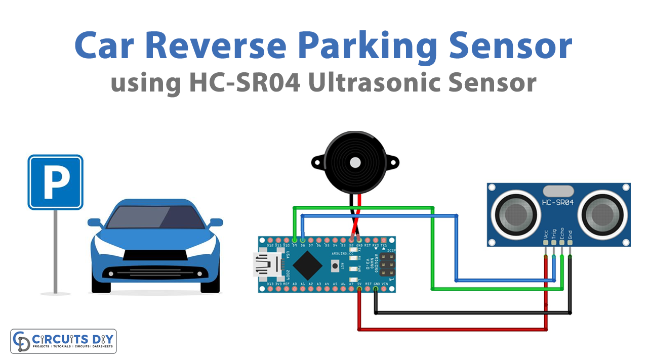
Circuit Diagram

Connection Table
| Arduino | HC-SR04 | Buzzer |
|---|---|---|
| GND | GND | GND |
| 5V | Vcc | |
| D8 | Echo | |
| D9 | Trig | |
| D2 | Positive |
Arduino Code
#define trigPin 8
#define echoPin 9
#define Buzzer 2

void setup() {
Serial.begin (9600);
pinMode(trigPin, OUTPUT);
pinMode(echoPin, INPUT);
pinMode(Buzzer, OUTPUT);

}

void loop() {

digitalWrite(trigPin, LOW);
delayMicroseconds(2);
digitalWrite(trigPin, HIGH);
delayMicroseconds(10);
digitalWrite(trigPin, LOW);

duration = pulseIn(echoPin, HIGH);

distance = (duration/2) / 29.1;

if (distance < 100)
{
digitalWrite(Buzzer,HIGH); //less than 100cm then buzzer will produce beep sound

}
else {
digitalWrite(Buzzer,LOW);
}

if (distance >= 300 || distance <= 0)
{
Serial.println("Out of range");
}
else {
Serial.print(distance);
Serial.println(" cm");
}
delay(500);
}
Working Explanation
In this Car Reverse parking sensor circuit we are using Arduino Nano. Thus, we are interfacing the nano board with the ultrasonic sensor HC-SR04. As we know that the ultrasonic sensor has two modules, a transmitter, and a receiver. There is also an inbuilt control circuit. This ultrasonic sensor sends eight 40KHz signals and detects if there is a pulse signal back. Hence, if there is any signal back present, the sensor gives a high level out. Now, to make the circuit follow the above-given circuit diagram and Connect the 5V supply from the nano board to the VCC of the ultrasonic sensor. And, connect the Ground of Arduino to the ground of the ultrasonic sensor. Connect the trig pin of the sensor to the D8 pin of Arduino and the Echo pin to the D9 pin of Arduino Nano. As per the circuit and Arduino code. Connect the buzzer. After uploading the code you can observe the readings on the serial monitor.
Code Explanation
- First, define the sensor pins that are connected to the digital pins of Arduino. Also, define the pin at which the buzzer is connected.
- In the void setup, initialize the serial monitor, and define the pin input-output pin mode.
- In a void loop, write the main code. Define your distance through the formula. After that, apply the if else condition to get the buzzer ON and OFF.
Application and Uses
- It has automotive applications
- Also, in robotic applications
- In cars and other vehicles
Related posts:
 Read/Write Serial EEPROM via I2C - Arduino
 How to Interface Mini SD Card Module with Arduino UNO
 How to Interface Arduino Ethernet Web Server with Relay
 Interface BMP180 Barometric Pressure & Temperature Sensor with Arduino
 How Rain Sensor Interface with Arduino UNO
 Relay control with Button - Arduino Tutorial