Introduction
In the previous years, when people do groceries, they have to wait long in the lines, because manual price count takes a lot of time. Thanks to the RFID technology, which helps to complete the process quicker. RFID, that is the Radio Frequency Identification technology which includes the tag and the reading machine. Hence the tag and the reader have a transmitter and a receiver respectively. To understand the complete procedure of this technology that how it works, In this tutorial, we are going to interface ” RC522 RFID Module with Arduino UNO”.
How RFID works?
You have noticed that when you want to purchase anything from the store, it has a tag on it. You give that thing to the cashier and he brings it in front of the reading machine that has a receiver in it. The tag has a microchip in it which stores the information or data. While the receiver has antennas that ensure the creation of high-frequency electromagnetic fields. This field powered the chip of the tag. Further, the tag transfers the information or data through the radio signals.
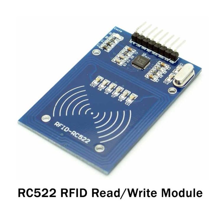
An Overview about RC522 Module
RC522 module comprises an RFID reader, RFID card, and a key chain. The module can operate at the industrial band frequency of 13.56 MHz. The keychain of the module has a memory of 1kB to store the information or data. Also, the reader of the module can both read and write the data. However, reading of the data can be done only from the passive tags that operate on the frequency of 13.56MHz.
Features of RC522 RFID Module
- The module has an operating range of 2.5V to 3.3V
- it has a maximum data range of 10Mbps
- it can read the data within 5cm
- the module consumes the current from 13 to 26mA
Hardware Required
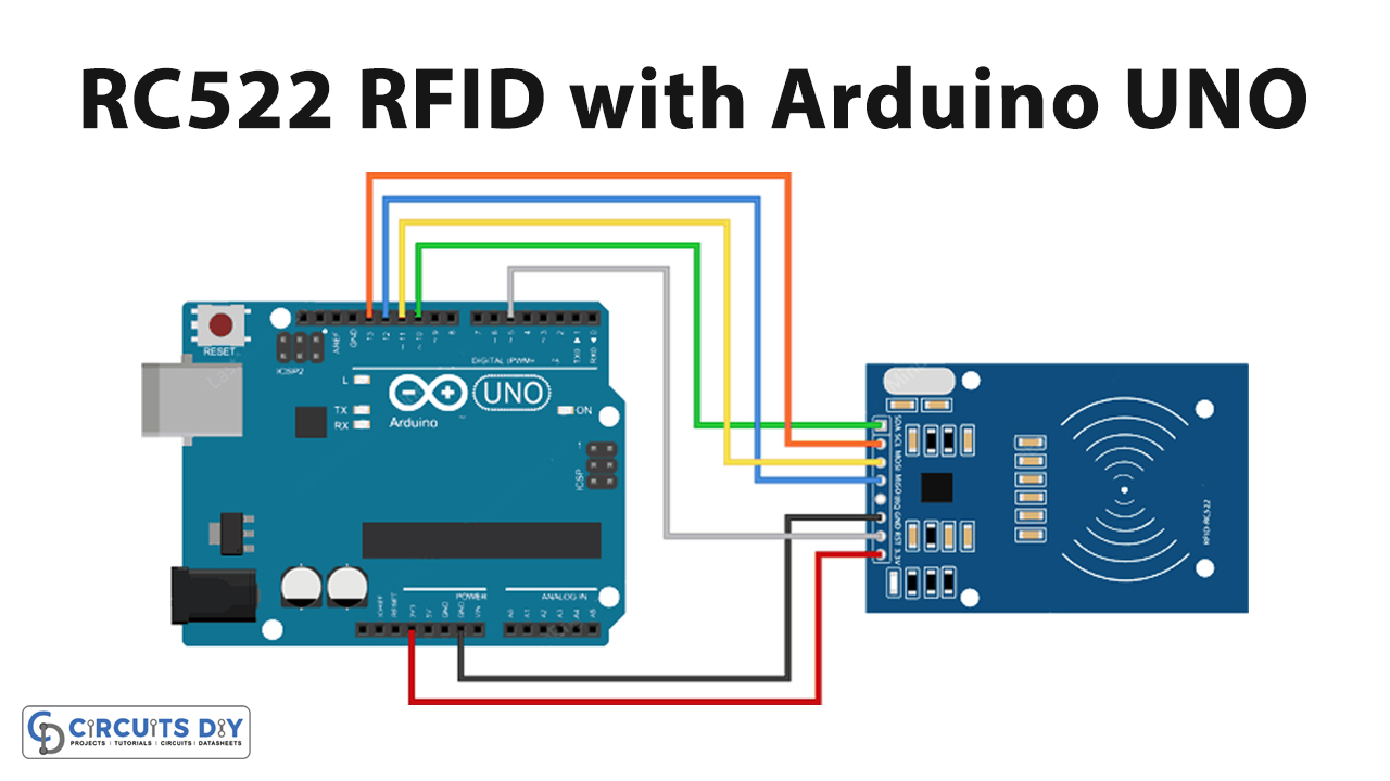
Circuit Diagram

Connection Table
| Arduino | RC522 RFID Module |
|---|---|
| 3.3V | VCC |
| D5 | RST |
| GND | GND |
| – | IRQ |
| D12 | MISO |
| D11 | MOSI |
| D13 | SCL |
| D10 | SDA |
Arduino Code
#include <SPI.h>      //include the SPI bus library
#include <MFRC522.h>  //include the RFID reader library

#define SS_PIN 10  //slave select pin
#define RST_PIN 5  //reset pin

MFRC522 mfrc522(SS_PIN, RST_PIN);  // instatiate a MFRC522 reader object.
MFRC522::MIFARE_Key key;          //create a MIFARE_Key struct named 'key', which will hold the card information

//this is the block number we will write into and then read.
int block=2;

byte blockcontent[16] = {"Last-Minute-Engg"};  //an array with 16 bytes to be written into one of the 64 card blocks is defined
//byte blockcontent[16] = {0,0,0,0,0,0,0,0,0,0,0,0,0,0,0,0};  //all zeros. This can be used to delete a block.

//This array is used for reading out a block.
byte readbackblock[18];

void setup()
{
    Serial.begin(9600);        // Initialize serial communications with the PC
    SPI.begin();               // Init SPI bus
    mfrc522.PCD_Init();        // Init MFRC522 card (in case you wonder what PCD means: proximity coupling device)
    Serial.println("Scan a MIFARE Classic card");

  // Prepare the security key for the read and write functions.
  for (byte i = 0; i < 6; i++) {
    key.keyByte[i] = 0xFF;  //keyByte is defined in the "MIFARE_Key" 'struct' definition in the .h file of the library
  }
}

void loop()
{
  // Look for new cards
  if ( ! mfrc522.PICC_IsNewCardPresent()) {
    return;
  }

  // Select one of the cards
  if ( ! mfrc522.PICC_ReadCardSerial())
  {
    return;
  }
    Serial.println("card selected");

   //the blockcontent array is written into the card block
   writeBlock(block, blockcontent);

   //read the block back
   readBlock(block, readbackblock);
   //uncomment below line if you want to see the entire 1k memory with the block written into it.
   //mfrc522.PICC_DumpToSerial(&(mfrc522.uid));

   //print the block contents
   Serial.print("read block: ");
   for (int j=0 ; j<16 ; j++)
   {
     Serial.write (readbackblock[j]);
   }
   Serial.println("");
}


//Write specific block
int writeBlock(int blockNumber, byte arrayAddress[])
{
  //this makes sure that we only write into data blocks. Every 4th block is a trailer block for the access/security info.
  int largestModulo4Number=blockNumber/4*4;
  int trailerBlock=largestModulo4Number+3;//determine trailer block for the sector
  if (blockNumber > 2 && (blockNumber+1)%4 == 0){Serial.print(blockNumber);Serial.println(" is a trailer block:");return 2;}
  Serial.print(blockNumber);
  Serial.println(" is a data block:");

  //authentication of the desired block for access
  byte status = mfrc522.PCD_Authenticate(MFRC522::PICC_CMD_MF_AUTH_KEY_A, trailerBlock, &key, &(mfrc522.uid));
  if (status != MFRC522::STATUS_OK) {
         Serial.print("PCD_Authenticate() failed: ");
         Serial.println(mfrc522.GetStatusCodeName(status));
         return 3;//return "3" as error message
  }

  //writing the block
  status = mfrc522.MIFARE_Write(blockNumber, arrayAddress, 16);
  //status = mfrc522.MIFARE_Write(9, value1Block, 16);
  if (status != MFRC522::STATUS_OK) {
           Serial.print("MIFARE_Write() failed: ");
           Serial.println(mfrc522.GetStatusCodeName(status));
           return 4;//return "4" as error message
  }
  Serial.println("block was written");
}


//Read specific block
int readBlock(int blockNumber, byte arrayAddress[])
{
  int largestModulo4Number=blockNumber/4*4;
  int trailerBlock=largestModulo4Number+3;//determine trailer block for the sector

  //authentication of the desired block for access
  byte status = mfrc522.PCD_Authenticate(MFRC522::PICC_CMD_MF_AUTH_KEY_A, trailerBlock, &key, &(mfrc522.uid));

  if (status != MFRC522::STATUS_OK) {
         Serial.print("PCD_Authenticate() failed (read): ");
         Serial.println(mfrc522.GetStatusCodeName(status));
         return 3;//return "3" as error message
  }

//reading a block
byte buffersize = 18;//we need to define a variable with the read buffer size, since the MIFARE_Read method below needs a pointer to the variable that contains the size...
status = mfrc522.MIFARE_Read(blockNumber, arrayAddress, &buffersize);//&buffersize is a pointer to the buffersize variable; MIFARE_Read requires a pointer instead of just a number
  if (status != MFRC522::STATUS_OK) {
          Serial.print("MIFARE_read() failed: ");
          Serial.println(mfrc522.GetStatusCodeName(status));
          return 4;//return "4" as error message
  }
  Serial.println("block was read");
}
Working Explanation
To Interface RC522 RFID Module with Arduino UNO, connect the circuit according to the diagram given above. Write the code in the Arduino software and upload it to Arduino UNO. Observe the reading in the serial monitor.
Code Explanation
- Download the SPI and MFRC522 libraries. You can download the library from:
https://github.com/miguelbalboa/rfid
- Include both the libraries. Define the module pins that are connected with the pins of an Arduino. Create the MFRC522 object. After that, create the MIFARE_Key structure key to hold the coming data. Declare the integer block to store the data. Now, define the sixteen-byte array blockcontent[16] to hold the message. the, define 18-byte array readbackblock[18] to read the written data.
- In the void setup, initialize the serial communication and SPI bus using begin functions. Initialize the card by using PCD_Init( ). Print the message by using Serial. println( ). Prepared the security key. This given key is the stored-in key function that we have defined above.
- In the void loop, give the if conditions to return the function if the card is not present or if it doesn’t read card serial. Call custom functions writeblock( ) and roadblock( ) to read or write the block contents. Finally, using the loop print the read block content.
Application and Uses
- It is utilized for automatic billing system
- Also, in attendance systems.
- In identification devices.