Introduction
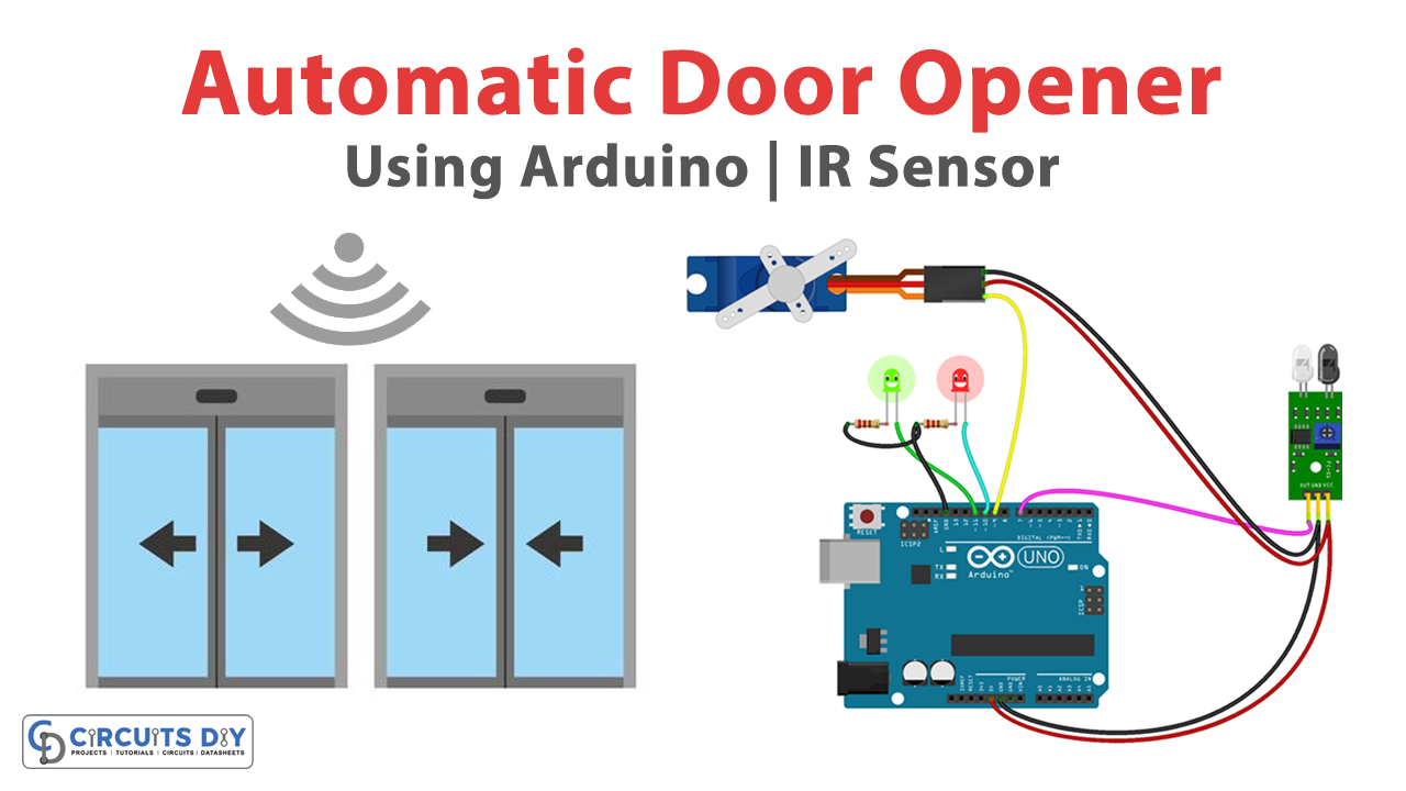
An IR-controlled Automatic Door Opener with stepper motors and Arduino UNO microcontroller is an advanced and efficient system designed to provide a hands-free solution for opening and closing doors in public places such as hospitals, commercial buildings, and other establishments. This innovative system utilizes an Arduino UNO microcontroller board to control precise stepper motors that allow for smooth and controlled door operation, while an IR sensor detects the presence of an individual and triggers the automatic opening or closing of the door.
With its advanced features and automated capabilities, this system provides a convenient and efficient solution for managing the flow of traffic in busy public areas.
Hardware Components
You will require the following hardware Automatic Door Opener.
| Components | Value | Qty |
|---|---|---|
| Arduino UNO | – | 1 |
| Servo Motor | SG90 | 1 |
| IR Sensor | – | 1 |
| LEDs | – | 2 |
| Resistor | 220Ω | 2 |
| Breadboard | – | 1 |
| Jumper Wires | – | 1 |
Code Explanation
- Include the Servo library:
#include <Servo.h>
This library provides functions for controlling servo motors.
- Create a Servo object:
Servo s1;
This creates an instance of the Servo class called “s1”.
- Declare a variable for the IR sensor output:
int val = 0;
This declares an integer variable “val” and initializes it to 0.
- Set up the Arduino in the
setup()function:
void setup() {
  Serial.begin(9600);
  s1.attach(3);
  pinMode(2, INPUT);
  pinMode(5, OUTPUT);
  pinMode(6, OUTPUT);
}
This function runs once when the Arduino is powered on or reset. It initializes the serial communication at 9600 baud, attaches the servo motor to pin 3, sets pin 2 as an input for the IR sensor output, and sets pins 5 and 6 as outputs for the LEDs.
- Control the servo motor in the
loop()function:
void loop() {
  val = digitalRead(2);
  Serial.println(val);
  delay(1);

  if (val == 1) {
    digitalWrite(5, HIGH);
    digitalWrite(6, LOW);
    s1.write(90);
    delay(2000);
  }
  else {
    digitalWrite(5, LOW);
    digitalWrite(6, HIGH);
    s1.write(0);
  }
}
This function runs repeatedly as long as the Arduino is powered on. It reads the value of pin 2, prints it to the serial monitor, and introduces a delay of 1 millisecond. If the value is 1 (meaning the IR sensor detected an object), the green LED turns on, the red LED turns off, the servo motor rotates to 90 degrees, and there is a delay of 2 seconds. If the value is 0 (meaning the IR sensor did not detect an object), the green LED turns off, the red LED turns on, and the servo motor rotates to 0 degrees.
Schematic
Make connections according to the circuit diagram given below.

Installing Arduino IDE
First, you need to install Arduino IDE Software from its official website Arduino. Here is a simple step-by-step guide on “How to install Arduino IDE“.
Installing Libraries
Before you start uploading a code, download and unzip the following libraries at /Program Files(x86)/Arduino/Libraries (default), in order to use the sensor with the Arduino board. Here is a simple step-by-step guide on “How to Add Libraries in Arduino IDE“.
Code
Now copy the following code and upload it to Arduino IDE Software.
#include <Servo.h>
Servo s1;
int val = 0 ;
void setup()
{
    Serial.begin(9600); // sensor buart rate
    s1.attach(3);
    pinMode(2,INPUT);
    pinMode(5,OUTPUT);  // led green pin
    pinMode(6,OUTPUT);  // led red pin
}
void loop()
{
  val = digitalRead(2);  // IR sensor output pin connected
  Serial.println(val);   // see the value in serial mpnitor in Arduino IDE
  delay(1);

  if(val == 1 )
  {
    digitalWrite(5,HIGH);  // LED ON
    digitalWrite(6,LOW);   // LED OFF
    s1.write(90);
    delay(2000);

  }
  else
  {
    digitalWrite(5,LOW);   // LED OFF
    digitalWrite(6,HIGH);  // LED ON
    s1.write(0);

  }
  }
Working Explanation
The Servo library is used to control the servo motor connected to pin 3. The IR sensor output is connected to pin 2 and the LED green and red pins are connected to pins 5 and 6 respectively. In the setup() function, the serial monitor is initialized with a baud rate of 9600, pin 3 is set as the output for the servo motor, and pins 2, 5, and 6 are set as input and output for the IR sensor and LEDs.
In the loop() function, the value of the IR sensor output pin is read using the digitalRead() function and printed to the serial monitor using the Serial.println() function. If the value of the IR sensor is 1, the green LED is turned on, the red LED is turned off, and the servo motor is set to rotate at an angle of 90 degrees for a delay of 2 seconds using the digitalWrite() and s1.write() functions. If the value of the IR sensor is not 1, the red LED is turned on, the green LED is turned off, and the servo motor is set to rotate at an angle of 0 degrees using the digitalWrite() and s1.write() functions.
Applications
- Commercial Buildings
- Hospitals
- Public Places
- Accessibility
- Security