Introduction
A push button-controlled piezoelectric buzzer circuit is an electronic system that uses the capabilities of an Arduino Uno microcontroller to generate an auditory output from a piezoelectric buzzer based on the user’s input. It utilizes the digital inputs and outputs of the microcontroller to monitor the state of a push button switch and generates a sound from the piezoelectric buzzer based on the state of the switch.
The microcontroller continuously runs a program that reads the state of the push button switch using the digitalRead() function. Depending on the state of the switch, the microcontroller sends a high or low signal to the digital output pin connected to the piezoelectric buzzer using the digitalWrite() function.
Hardware Components
You will require the following hardware for Piezo Buzzer with Arduino.
| S.no | Component | Value | Qty |
|---|---|---|---|
| 1. | Arduino UNO | – | 1 |
| 2. | USB Cable Type A to B | – | 1 |
| 3. | Button | – | 1 |
| 4. | Piezo Buzzer | – | 1 |
| 5. | 9V Power Adapter for Arduino | – | 1 |
| 6. | Breadboard | – | 1 |
| 7. | Jumper Wires | – | 1 |
Piezo Buzzer with Arduino UNO
- Connect the 5V piezoelectric buzzer to the Arduino Uno board. The buzzer typically has two pins: one for the positive terminal (usually labeled “+” or “S”) and one for the negative terminal (usually labeled “-” or “N”). Connect the positive terminal to digital pin 8 and the negative terminal to one of the GND pins on the board.
- Connect the pushbutton to the Arduino board. The push button typically has two pins. Connect one pin to digital pin 2 and the other pin to one of the GND pins on the board.
- In your Arduino sketch, configure the buzzer pin as an output by adding the following line in the setup() function:
pinMode(8, OUTPUT);
- In the setup() function, configure the pushbutton pin as input by adding the following line:
pinMode(2, INPUT);
- In the loop() function, use the digitalRead() function to check the state of the pushbutton. If the button is pressed, use the tone() function to generate a tone on the buzzer pin:
if (digitalRead(2) == HIGH) {
    tone(8, 1000);
}
You can replace the frequency 1000 with the desired frequency in hertz, for example, 2000 for 2Khz.
- If you want to stop the sound when the button is released you can use
noTone(8)it is after the previous if statement.
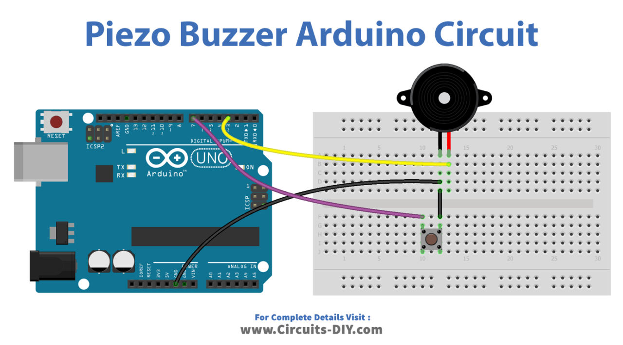
Schematic
Make connections according to the circuit diagram given below.
Installing Arduino IDE
First, you need to install Arduino IDE Software from its official website Arduino. Here is a simple step-by-step guide on “How to install Arduino IDE“.
Installing Libraries
Before you start uploading a code, download and unzip the following libraries at /Progam Files(x86)/Arduino/Libraries (default), in order to use the sensor with the Arduino board. Here is a simple step-by-step guide on “How to Add Libraries in Arduino IDE“.
- <a href=”http://” target=”_blank” rel=”noreferrer noopener”>pitches. h
Code
Now copy the following code and upload it to Arduino IDE Software.
Arduino Code – Simple Sound
const int BUTTON_PIN = 7; // Arduino pin connected to button's pin
const int BUZZER_PIN = 3; // Arduino pin connected to Buzzer's pin

void setup() {
  Serial.begin(9600);                // initialize serial
  pinMode(BUTTON_PIN, INPUT_PULLUP); // set arduino pin to input pull-up mode
  pinMode(BUZZER_PIN, OUTPUT);       // set arduino pin to output mode
}

void loop() {
  int buttonState = digitalRead(BUTTON_PIN); // read new state

  if (buttonState == LOW) {
    Serial.println("The button is being pressed");
    digitalWrite(BUZZER_PIN, HIGH); // turn on
  }
  else
  if (buttonState == HIGH) {
    Serial.println("The button is unpressed");
    digitalWrite(BUZZER_PIN, LOW);  // turn off
  }
}
Arduino Code – Melody
#include "pitches.h"

const int BUTTON_PIN = 7; // Arduino pin connected to button's pin
const int BUZZER_PIN = 3; // Arduino pin connected to Buzzer's pin

// notes in the melody:
int melody[] = {
  NOTE_E5, NOTE_E5, NOTE_E5,
  NOTE_E5, NOTE_E5, NOTE_E5,
  NOTE_E5, NOTE_G5, NOTE_C5, NOTE_D5,
  NOTE_E5,
  NOTE_F5, NOTE_F5, NOTE_F5, NOTE_F5,
  NOTE_F5, NOTE_E5, NOTE_E5, NOTE_E5, NOTE_E5,
  NOTE_E5, NOTE_D5, NOTE_D5, NOTE_E5,
  NOTE_D5, NOTE_G5
};

// note durations: 4 = quarter note, 8 = eighth note, etc, also called tempo:
int noteDurations[] = {
  8, 8, 4,
  8, 8, 4,
  8, 8, 8, 8,
  2,
  8, 8, 8, 8,
  8, 8, 8, 16, 16,
  8, 8, 8, 8,
  4, 4
};

void setup() {
  Serial.begin(9600);                // initialize serial
  pinMode(BUTTON_PIN, INPUT_PULLUP); // set arduino pin to input pull-up mode
}

void loop() {
  int buttonState = digitalRead(BUTTON_PIN); // read new state

  if (buttonState == LOW) { // button is pressed
    Serial.println("The button is being pressed");
    buzzer();
  }
}

void buzzer() {
  // iterate over the notes of the melody:
  int size = sizeof(noteDurations) / sizeof(int);

  for (int thisNote = 0; thisNote < size; thisNote++) {
    // to calculate the note duration, take one second divided by the note type.
    //e.g. quarter note = 1000 / 4, eighth note = 1000/8, etc.
    int noteDuration = 1000 / noteDurations[thisNote];
    tone(BUZZER_PIN, melody[thisNote], noteDuration);

    // to distinguish the notes, set a minimum time between them.
    // the note's duration + 30% seems to work well:
    int pauseBetweenNotes = noteDuration * 1.30;
    delay(pauseBetweenNotes);
    // stop the tone playing:
    noTone(BUZZER_PIN);
  }
}
Working Explanation
The setup() function is executed once at the start of the program and is used to set the initial conditions for the microcontroller. In this case, it is used to configure the microcontroller’s pins for the push button switch and piezoelectric buzzer. For example, the pin connected to the push button switch is configured as an input pin using the pinMode(buttonPin, INPUT) function, and the pin connected to the piezoelectric buzzer is configured as an output pin using the pinMode(buzzerPin, OUTPUT) function.
The loop() function monitors the state of the push button switch and controls the output to the piezoelectric buzzer based on the state of the switch. The digitalRead(buttonPin) function is used to read the state of the push button switch and the digitalWrite(buzzerPin, state) function is used to control the state of the piezoelectric buzzer. For example, if the push button switch is pressed, the code sets the state of the piezoelectric buzzer to high using digitalWrite(buzzerPin, HIGH), which causes the buzzer to generate sound, and when the button is not pressed, the code sets the state of the piezoelectric buzzer to low using digitalWrite(buzzerPin, LOW) which stops the sound.
Applications
- Robotics
- Safety and emergency systems
- Medical equipment
- Education and experimentation
- Personal projects and DIY devices
Conclusion.
We hope you have found this Arduino Piezo Buzzer Circuit very useful. If you feel any difficulty in making it feel free to ask anything in the comment section.