Introduction
Often times in electronic devices we need to display the data or show the message to the user of the device. And hence for this purpose display screens like LCDs are employed. This article would be all about LCDs. Thus we’ll work on Displaying Sensor Values on LCD 16×2.
The basic technology behind these displays is multi-segment light-emitting diodes. Since these LCD modules are inexpensive and easy to program, they are frequently utilized in DIY embedded applications.
What is a 16×2 LCD?
16×2 LCD is a type of electronic gadget that displays messages and data. Liquid Crystal Display is the term’s entire meaning. The reason the 162 LCD is thus named is that it contains 16 Columns and 2 Rows. It can show a total of (16 + 2) 32 characters, each of which is composed of 5 x 8 pixels. There are other combinations available, including 8×1, 8×2, 10×2, 16×1, etc., but the 16×2 LCD is the most popular.
Hardware Components
You will require the following hardware for Displaying Sensor Values on LCD.
| S.no | Component | Value | Qty |
|---|---|---|---|
| 1. | Arduino | UNO | 1 |
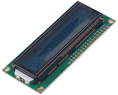
| 2. | LED White on Blue | 16×2 | 1 |
| 3. | Rotary Potentiometer | – | 1 |
| 4. | Trim Potentiometer | RM065 10KΩ 103 | 1 |
| 5. | Trim Potentiometer | RM065 1KΩ 102 | 1 |
| 6. | Resistor | Ω | 1 |
| 7. | Breadboard | – | 1 |
| 8. | Jumper Wires | – | 1 |
Steps Displaying Sensor Values on LCD
For Displaying Sensor Values on LCD 16×2, you need an LCD and Arduino along with some basic electronic components. Once you get them all; follow the given steps:
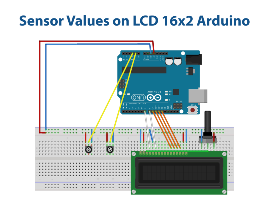
Schematic
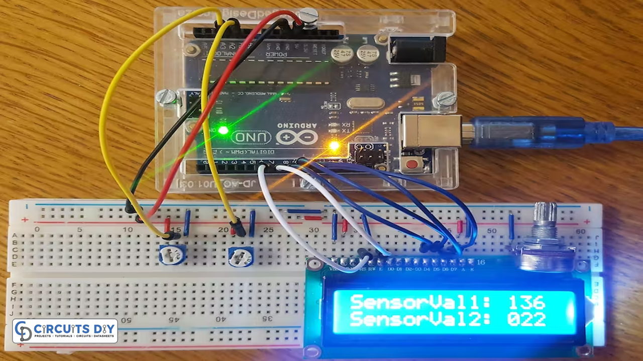
Make connections according to the circuit diagram given below.
Installing Arduino IDE
First, you need to install Arduino IDE Software from its official website Arduino. Here is a simple step-by-step guide on “How to install Arduino IDE“.
Installing Libraries
Before you start uploading a code, download and unzip the following libraries at /Progam Files(x86)/Arduino/Libraries (default), in order to use the sensor with the Arduino board. Here is a simple step-by-step guide on “How to Add Libraries in Arduino IDE“.
Code
Now copy the following code and upload it to Arduino IDE Software.
// include the library code:
#include <LiquidCrystal.h>

// initialize the library with the numbers of the interface pins
LiquidCrystal lcd(7,8,9,10,11,12);

int potPin1 = A1;
int potPin2 = A2;

void setup()
{
// set up the LCD's number of columns and rows:
lcd.begin(16, 2);
lcd.clear();

pinMode(potPin1, INPUT);
pinMode(potPin2, INPUT);
}

void loop()
{
lcd.setCursor(0,0); // Sets the cursor to col 0 and row 0
lcd.print("SensorVal1: "); // Prints Sensor Val: to LCD
lcd.print(analogRead(potPin1)); // Prints value on Potpin1 to LCD
lcd.setCursor(0,1); // Sets the cursor to col 1 and row 0
lcd.print("SensorVal2: "); // Prints Sensor Val: to LCD
lcd.print(analogRead(potPin2)); // Prints value on Potpin1 to LCD
Let’s Test It
After you make connections and upload the code, it’s now time to test the circuit. Power up the Arduino. Two lines on the LCD will show up; these are the t the potentiometer values. To ensure the LCD brightness is ideal for reading the values, you can adjust the B10K potentiometer.
Working Explanation
To understand the working of the circuit, let’s dig into the coding:
- First, we include the library for LCD. Know that, it is absolutely necessary to include the library before writing further code.
- Then, we make the variables that define the analog pins that are connected to the two potentiometers.
- In the void setup, we use the function lcd.begin to initialize the LCD. We also clear the LCD to show the coming reading. For that purpose, we use lcd.clear function
- Then we declare the status of the Arduino pins that we defined above. In this project, both are working as inputs. We use the PinMode function for that purpose
- Then we set the cursor to row 0 and column 0 and print the phrase SensorVal1:. Then the code reads the value and prints the value of potentiometer one. Similarly, we set the cursor to row 0 and column 1 and print the phrase SensorVal2:. Then the code reads the value and prints the value of potentiometer two. To set the cursor lcd.setCursor function is used. To get the readings from the potentiometers, analogRead function is used. And, to print that reading lcd.print is used.
Applications
- Small electronic projects to display messages.
Conclusion.
We hope you have found this Displaying Sensor Values on LCD Circuit very useful. If you feel any difficulty in making it feel free to ask anything in the comment section.