Introduction
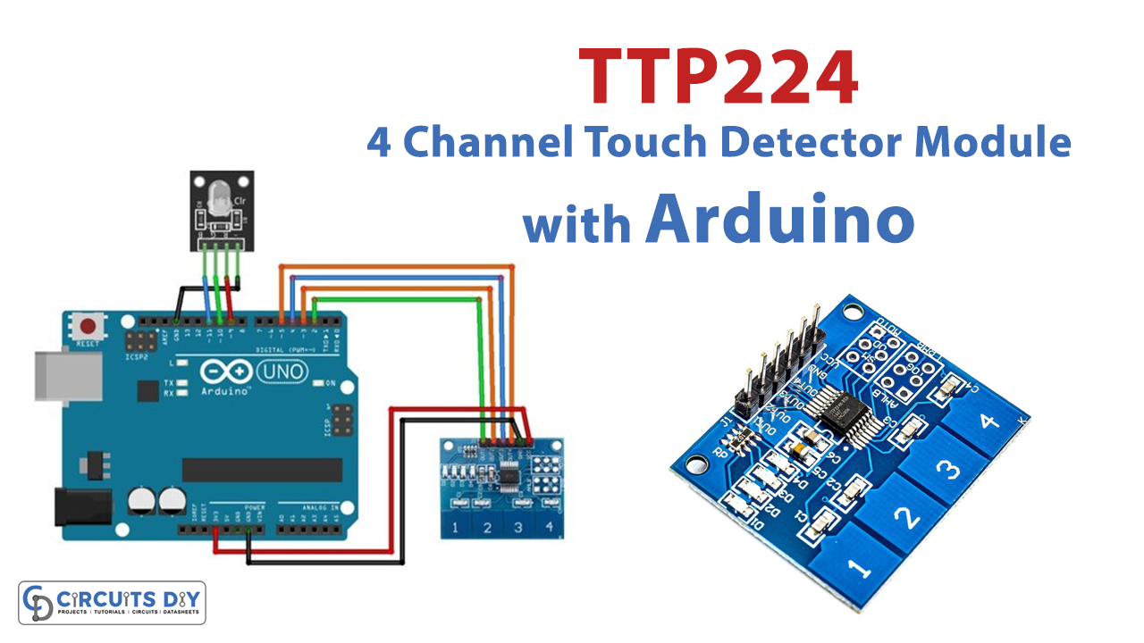
Nowadays, it’s common to see a display or Arduino project with a touch detector. Are you interested in learning the basics of touch sensors and integrating them with your Arduino? If yes, stick to this article because, in this tutorial, we will make a “TTP224 Four-Channel Touch Detector Module with Arduino.”
When you have finished going through this tutorial, you will be able to construct a circuit capable of detecting touch or proximity, most often by a human user. So, let’s just jump right in!
What is a Touch Detector?
Electronic sensors capable of detecting and recording touch input are known as “touch detectors.” It’s an inexpensive, simple sensor designed to take the role of mechanical switches. A touch sensor is similar to a switch in that it permits current to flow via an electrical circuit when there is contact, touch, or pressure on its surface.
Hardware Required
| Sr. No | Components | Value | Qty |
|---|---|---|---|
| 1 | Arduino | UNO | 1 |
| 2 | USB Cable | Type A to B | 1 |
| 3 | Digital Touch Sensor Module | TTP224 | 1 |
| 4 | Jumper Wires | – | |
| 5 | RGB Led Sensor Module | – | 1 |
Steps to make a Touch Detector Circuit
To make this touch detector circuit, you must first have the components listed in the hardware section. Once you have them all, follow the following steps:
Circuit Diagram

Connection Table
| TTP224 Module | Arduino UNO |
|---|---|
| GND | GND |
| VCC | +3V |
| OUT1 | D2 |
| OUT2 | D3 |
| OUT3 | D4 |
| OUT4 | D5 |
| RGB LED(common cathode) | Arduino UNO |
|---|---|
| GND | GND |
| R | D9(PWM) |
| G | D10(PWM) |
| B | D11(PWM) |
Arduino Code
#define PAD1 2 //Buttons pins
#define PAD2 3
#define PAD3 4
#define PAD4 5

//Arduino pins to which RGB LED connected
#define RED_LED 9
#define GREEN_LED 10
#define BLUE_LED 11

// Variables to store PWM duty cycle for each LED

int Red=0, Blue=0, Green=0; //Color values to be affected to the RGB

//Boolean variable to store pad state

bool PAD1_State, PAD2_State, PAD3_State, PAD4_State;


void setup() {

  Serial.begin(9600);        //Set Serial communication

  pinMode(PAD1,INPUT);    //Set pin modes
  pinMode(PAD2,INPUT);
  pinMode(PAD3,INPUT);
  pinMode(PAD4,INPUT);

  pinMode(RED_LED,OUTPUT);
  pinMode(GREEN_LED,OUTPUT);
  pinMode(BLUE_LED,OUTPUT);

}

void loop() {

  Serial.print(Red);     //Display the colors values on the serial monitor
  Serial.print("\t");
  Serial.print(Green);
  Serial.print("\t");
  Serial.println(Blue);


  PAD1_State = digitalRead(PAD1); //Read the buttons states
  PAD2_State = digitalRead(PAD2);
  PAD3_State = digitalRead(PAD3);
  PAD4_State = digitalRead(PAD4);

  analogWrite(RED_LED,Red);       //Write the values on the RGB
  analogWrite(GREEN_LED,Green);
  analogWrite(BLUE_LED,Blue);

  if(PAD1_State == HIGH)   //Button 1 controls the RED, 2 Green and 3 Blue
     Red+= 20;                //Everytime you press the value gets incremented by 20 you can change as you want
  if(Red >= 255)              //If it exceeds the limit it will be brought back to 0
     Red=0;

   if(PAD2_State == HIGH)
   Green+= 20;
  if(Green >= 255)
   Green=0;

   if(PAD3_State == HIGH)
   Blue+= 20;
   if(Blue >= 255)
   Blue=0;

   if(PAD4_State == HIGH){ //Button 4 resets the value to 0

    Red=0;
    Green=0;
    Blue=0;

   }
  delay(100); //To avoid that one touch gets counted as 10 or more, although 100 is pretty big you can reduce it and test
}
Let’s Test!
After wiring the circuit and uploading the above-given code, it’s time to test it. So, as soon as the Arduino gets the power, the circuit turns on. And now, if someone touched the sensor, RGB LED would turn on according to the given state in the code.
Working Explanation
So, understanding the working of this circuit requires an understanding of code since it is the code on which the circuit depends. So, let us briefly discuss the working of code.
- In the code, we first define and name the button pins( PAD1, PAD2, PAD3, PAD4) that are connected to the Arduino.
- Then we define and name the Arduino pins connected to the RGB LED pins.
- Following that, we define three integers (Red, blue, green) that would store the color values.
- Also, to store pad state, we define three boolean variable
- Now comes the void setup. In the void setup, we first initialize the serial monitor. In addition to that, we declared the status of te defined pins. All the sensor pins are defined as input ( since we are taking input from the sensor). All the RGB pins are defined as output (because we shoe output through RGB LED)
- In the void loop, we first display the color values on the serial monitor using the function serial.print. To read the button states means the values coming from the sensor, we use the digitalRead function. Also, we store those values in other variables (PAD1_State, PAD2_State, PAD3_State, PAD3_State) And, then to write those readings on RGB LED, meaning to show the reading through LED, we give the function analogWrite.
- Now, which LED should glow? For this, we provide different conditions. For example, if the pad1 state is high, the value of the red LED would be incremented by 20, and if the value exceeds the defined value, i.e., 250, the value would become zero. Similarly, PAD 2 and PAD3 control green and blue LEDs, respectively. If Pad 4 is high, all the LEDs will be reset.
- In the end, we give a little delay to get the next value.
Application and Uses
- Home Appliances Control
- Various consumer products