Introduction
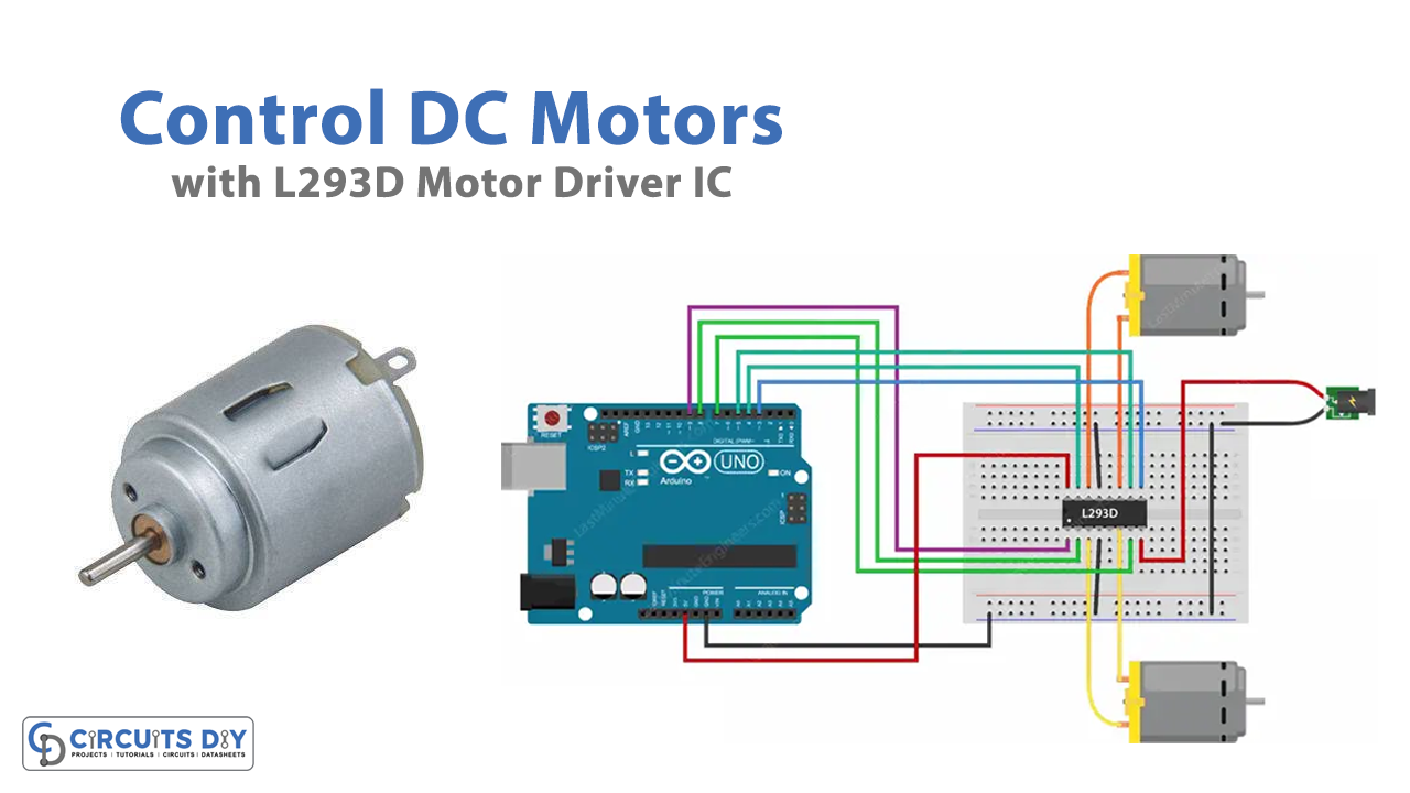
DC motors have wide use in electrical, electronics, and mechanical industries. Shafts, vacuum cleanses, conveyors, washing machines, printing machines, and many other machines used DC motors in them. However, controlling DC motors is need to be understood properly, because every machine has to be derived and controlled differently. Thus, there are different driver ICs available that with the help of microcontrollers like Arduino controlled the DC motors in a better and more precise way. Therefore, in this tutorial, we are going to control DC Motors with L293D Motor Driver with Arduino UNO.
L293d is a motor driver IC that can drive two DC motors. We use microcontrollers along with this IC to control the direction. This motor driver IC can drive a motor having voltages less than 36V. Moreover, the IC can run the motors in both directions, either clockwise, or anti-clockwise.
Hardware Required
| SR No | Components | Value | Qty |
|---|---|---|---|
| 1 | Arduino UNO | – | 1 |
| 2 | USB Cable Type A to B | – | 1 |
| 3 | Jumper Wires | – | – |
| 4 | Motor Driver IC | L293D | 1 |
| 5 | Bread Board | – | 1 |
| 6 | Battery | 9v | 1 |
Circuit Diagram

Connection Table
| Arduino | L293D Motor Driver |
|---|---|
| VCC | VCC |
| GND | GND |
| D9 | Pin 1 |
| D8 | Pin 2 |
| D7 | Pin 7 |
| D3 | Pin 9 |
| D5 | Pin 10 |
| D4 | Pin 15 |
Pin Configuration of L293D Motor Driver IC
| Pin Number | Pin Name | Description |
| 1 | Enable 1,2 | This pin enables the input pin Input 1(2) and Input 2(7) |
| 2 | Input 1 | Directly controls the Output 1 pin. Controlled by digital circuits. |
| 3 | Output 1 | Connected to one end of Motor 1 |
| 4 | Ground | We connect ground pins to the ground of the circuit (0V) |
| 5 | Ground | Ground pins are connected to the ground of the circuit (0V) |
| 6 | Output 2 | Connected to another end of Motor 1 |
| 7 | Input 2 | Directly controls the Output 2 pin. Controlled by digital circuits. |
| 8 | Vcc2 (Vs) | Connected to Voltage pin for running motors (4.5V to 36V) |
| 9 | Enable 3,4 | This pin enables the input pin Input 3(10) and Input 4(15) |
| 10 | Input 3 | Directly controls the Output 3 pin. Controlled by digital circuits |
| 11 | Output 3 | Connected to one end of Motor 2 |
| 12 | Ground | We connect ground pins to the ground of the circuit. |
| 13 | Ground | We connect ground pins to the ground of the circuit. |
| 14 | Output 4 | Connected to another end of Motor 2 |
| 15 | Input 4 | Directly controls the Output 4 pin. Controlled by digital circuits |
| 16 | Vcc2 (Vss) | Connected to +5V to enable IC function |
Arduino Code
// Motor A connections
int enA = 9;
int in1 = 8;
int in2 = 7;
// Motor B connections
int enB = 3;
int in3 = 5;
int in4 = 4;

void setup() {
	// Set all the motor control pins to outputs
	pinMode(enA, OUTPUT);
	pinMode(enB, OUTPUT);
	pinMode(in1, OUTPUT);
	pinMode(in2, OUTPUT);
	pinMode(in3, OUTPUT);
	pinMode(in4, OUTPUT);

	// Turn off motors - Initial state
	digitalWrite(in1, LOW);
	digitalWrite(in2, LOW);
	digitalWrite(in3, LOW);
	digitalWrite(in4, LOW);
}

void loop() {
	directionControl();
	delay(1000);
	speedControl();
	delay(1000);
}

// This function lets you control spinning direction of motors
void directionControl() {
	// Set motors to maximum speed
	// For PWM maximum possible values are 0 to 255
	analogWrite(enA, 255);
	analogWrite(enB, 255);

	// Turn on motor A & B
	digitalWrite(in1, HIGH);
	digitalWrite(in2, LOW);
	digitalWrite(in3, HIGH);
	digitalWrite(in4, LOW);
	delay(2000);

	// Now change motor directions
	digitalWrite(in1, LOW);
	digitalWrite(in2, HIGH);
	digitalWrite(in3, LOW);
	digitalWrite(in4, HIGH);
	delay(2000);

	// Turn off motors
	digitalWrite(in1, LOW);
	digitalWrite(in2, LOW);
	digitalWrite(in3, LOW);
	digitalWrite(in4, LOW);
}

// This function lets you control speed of the motors
void speedControl() {
	// Turn on motors
	digitalWrite(in1, LOW);
	digitalWrite(in2, HIGH);
	digitalWrite(in3, LOW);
	digitalWrite(in4, HIGH);

	// Accelerate from zero to maximum speed
	for (int i = 0; i < 256; i++) {
		analogWrite(enA, i);
		analogWrite(enB, i);
		delay(20);
	}

	// Decelerate from maximum speed to zero
	for (int i = 255; i >= 0; --i) {
		analogWrite(enA, i);
		analogWrite(enB, i);
		delay(20);
	}

	// Now turn off motors
	digitalWrite(in1, LOW);
	digitalWrite(in2, LOW);
	digitalWrite(in3, LOW);
	digitalWrite(in4, LOW);
}
Working Explanation
To Control DC Motors with L293D Motor Driver IC & Arduino first make the connections perfectly as described in the table and circuit diagram. Then, after that, write the given code in your Arduino IDE and upload that code to your Arduino. Now, when you give the supply to the circuit, the motor starts to rotate according to the commands provided in the code. For example, those motors start rotating at full speed in one direction, then in the other direction, for two seconds respectively. Then they stop rotating. After that, they accelerate from 0 to maximum speed, then decelerate back to zero. Hence, the motors get controlled according to your code.
Code Explanation
- This code doesn’t require any library. So, in the start, we first declared the Arduino pins which are connected with the driver pins.
- In the void setup, we declared all those pins as the output pin to get the output. Moreover, we initially set them low.
- In the void loop, we provide different functions. For example, direction control() has a function to spin the motors for two seconds at full speed. It then spins the motors in the opposite direction for another two seconds. Finally, the motors are turned off. The function speed control() accelerates both motors from 0 to maximum speed, then decelerates them back to zero. Finally, the motors are turned off.
Application and Uses
- In robotics for the movement of robots, or robotic cars.
- In the industries for conveyer belts, Printing machines, etc.
- In consumer electronics like a vacuum cleaner, Etc