Introduction
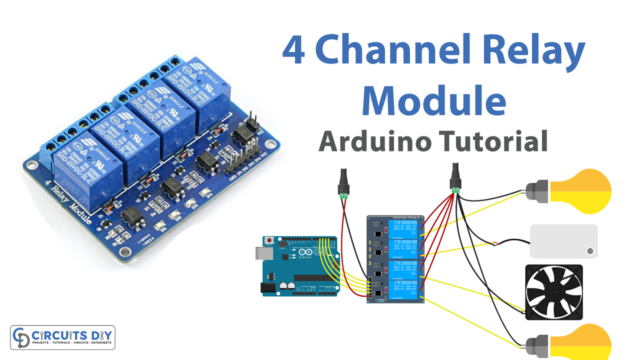
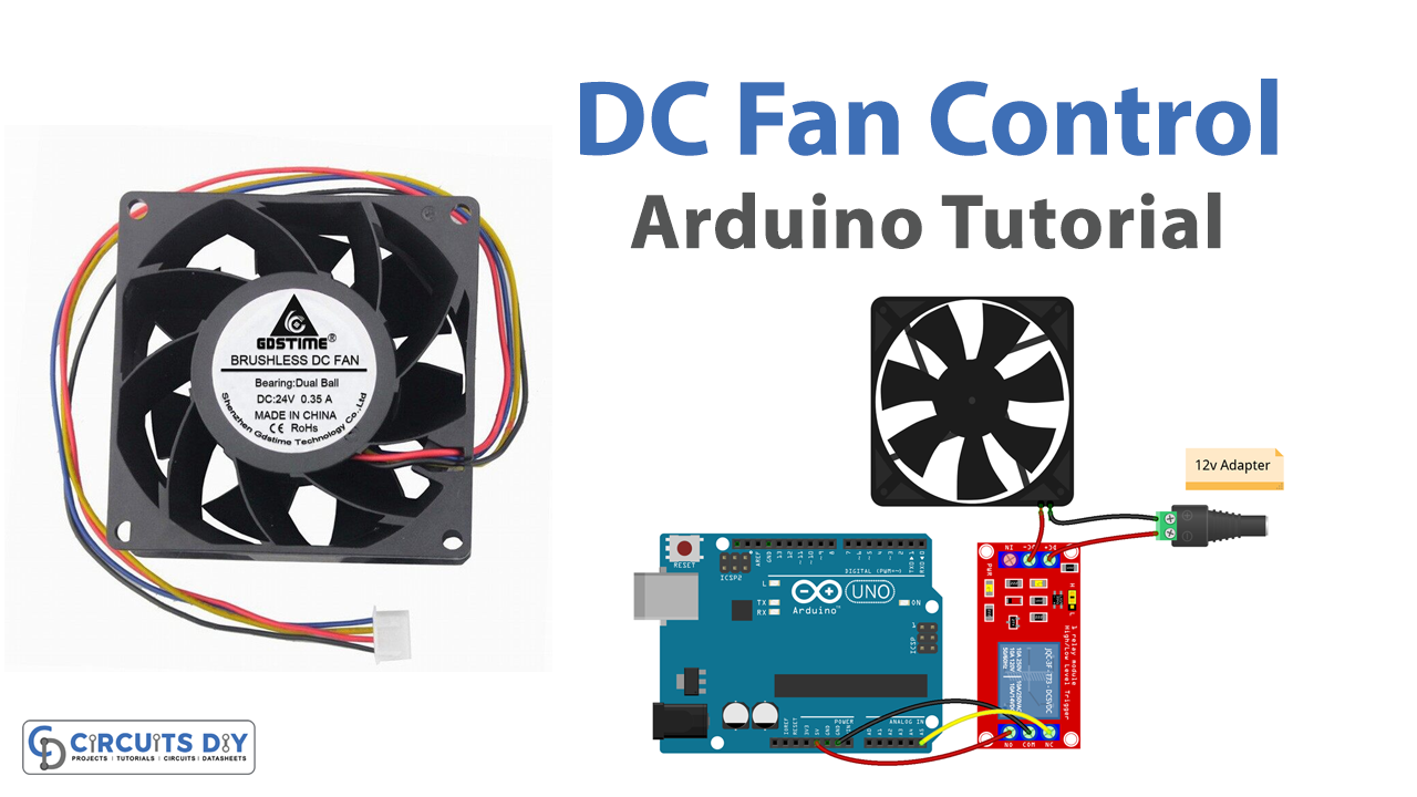
Interfacing a 5V SPDT relay module with an Arduino UNO microcontroller to control a 12V DC fan is a powerful and versatile solution for controlling and automating electrical devices. This system allows for remote control of a 12V DC fan by using the digital output of an Arduino microcontroller to switch the fan on or off through a relay module.
The relay module serves as an electronic switch that can be controlled by the digital signal generated by the Arduino. It has a single common contact and two normally open and normally closed contacts, which allows the user to switch the state of the fan.
Hardware Components
You will require the following hardware for Controlling a DC Fan with Arduino.
| S.no | Component | Value | Qty |
|---|---|---|---|
| 1. | Arduino UNO | – | 1 |
| 2. | USB Cable Type A to B | – | 1 |
| 3. | Relay | – | 1 |
| 4. | Cooling Fan | 12V | 1 |
| 5. | Power Adapter | 12V | 1 |
| 6. | DC Power Jack | – | 1 |
| 7. | Power Adapter for Arduino | 9V | 1 |
| 8. | Jumper Wires | – | 1 |
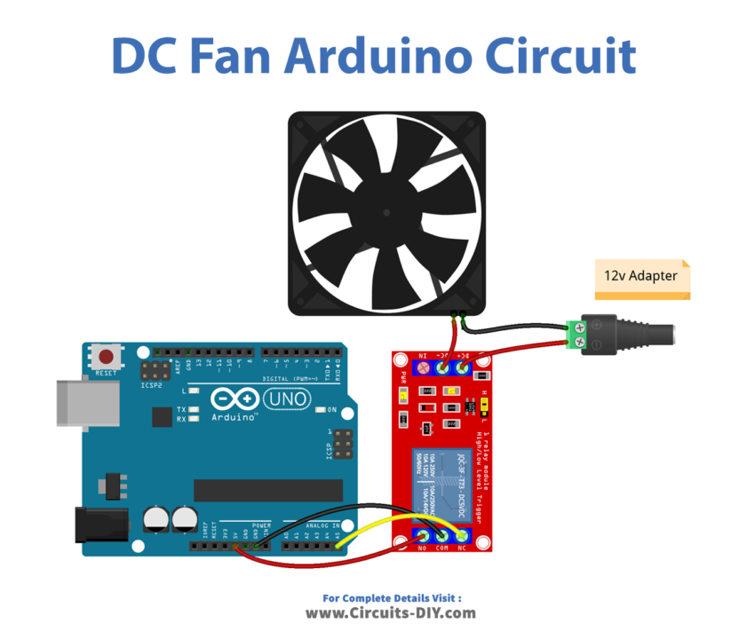
DC Fan with Arduino
- Connect the 5V SPDT relay module to the Arduino Uno as follows:
- VCC pin to 5V
- IN1 pin to digital pin 2
- GND pin to GND
- Connect the 12V DC fan to the relay module as follows:
- Connect the positive terminal of the fan to the NC (Normally Closed) pin of the relay
- Connect the negative terminal of the fan to the GND
- Define the pin number for the relay in the setup function:
int relayPin = 2;
- In the setup function, set the relay pin as an output using the
pinMode()function and initialize the serial communication using theSerial.begin()function:
pinMode(relayPin, OUTPUT);
Serial.begin(9600);
- In the loop function, use the
digitalWrite()function to control the state of the relay. For example, to turn on the fan:
digitalWrite(relayPin, HIGH);
- To turn off the fan:
digitalWrite(relayPin, LOW);- To post the status of the fan on the serial monitor, use the
Serial.println()function:
if (digitalRead(relayPin) == HIGH) {
  Serial.println("Fan is on");
} else {
  Serial.println("Fan is off");
}
Schematic
Make connections according to the circuit diagram given below.
Wiring / Connections
| Arduino | Sensor |
|---|---|
| 5V | VCC |
| GND | GND |
| A5 | SIG PIN |
Installing Arduino IDE
First, you need to install Arduino IDE Software from its official website Arduino. Here is a simple step-by-step guide on “How to install Arduino IDE“.
Code
Now copy the following code and upload it to Arduino IDE Software.
const int RELAY_PIN = A5;  // the Arduino pin, which connects to the IN pin of relay

// the setup function runs once when you press reset or power the board
void setup() {
  // initialize digital pin A5 as an output.
  pinMode(RELAY_PIN, OUTPUT);
}

// the loop function runs over and over again forever
void loop() {
  digitalWrite(RELAY_PIN, HIGH); // turn on fan 5 seconds
  delay(5000);
  digitalWrite(RELAY_PIN, LOW);  // turn off fan 5 seconds
  delay(5000);
}
Working Explanation
In the setup function, the Arduino’s serial communication is initialized and the relay pin is defined and set as an output pin. This is done to ensure that the relay pin is ready to receive digital signals from the microcontroller. In the loop function, the digitalWrite() function is used to control the state of the relay. This function sends a digital signal to the relay pin, which in turn switches the state of the relay, turning the fan on or off.
The digitalRead() function is used to read the state of the relay. This function reads the digital signal from the relay pin and stores it in a variable. Then, the Serial.println() function is used to display the status of the fan on the serial monitor. This function displays the state of the fan on the serial monitor, whether it is on or off.
Applications
- Robotics
- Automotive
- Agriculture
- Smart City
- Safety and Security
- Medical
- Energy Management
Conclusion
We hope you have found this Arduino-based DC Control Circuit very useful. If you feel any difficulty in making it feel free to ask anything in the comment section.