Introduction
Are you ready to harness the sun’s power and add some sizzle to your projects? The ML8511 UV sensor module is here to help you do just that! With this nifty little gadget, you’ll be able to detect the intensity of ultraviolet (UV) radiation in the environment. Imagine building a sunscreen reminder device that keeps you safe from harmful UV rays or a UV index monitor that helps you plan your outdoor activities. The possibilities are endless with the ML8511 and Arduino by your side.
With the help of this little module, you’ll be able to detect the intensity of ultraviolet (UV) radiation in the environment and use that information to trigger all sorts of fun projects and applications. So let’s dive in and see how to get started with this amazing sensor module! Whether you’re a seasoned maker or new to DIY electronics, we’ll show you everything you need to know to bring your UV sensing projects to the next level. Let’s get started!
What is UV Sensor?
The ultraviolet (UV) sensor is a device that takes in ultraviolet light and transforms it into an electrical signal. These sensors determine the strength or intensity of ultraviolet radiation. They are transmitters that produce energy signals of a different sort in response to the UV signal they receive. UV sensors are used in various contexts, including robotics, automation, automobiles, etc.

Hardware Components
You will require the following hardware for Interfacing ML8511 UV Sensor Module with Arduino.
| S.no | Component | Value | Qty |
|---|---|---|---|
| 1. | Arduino UNO | – | 1 |
| 2. | UV Detection Module | ML8511 | 1 |
| 3. | Breadboard | – | 1 |
| 4. | Jumper Wires | – | 1 |
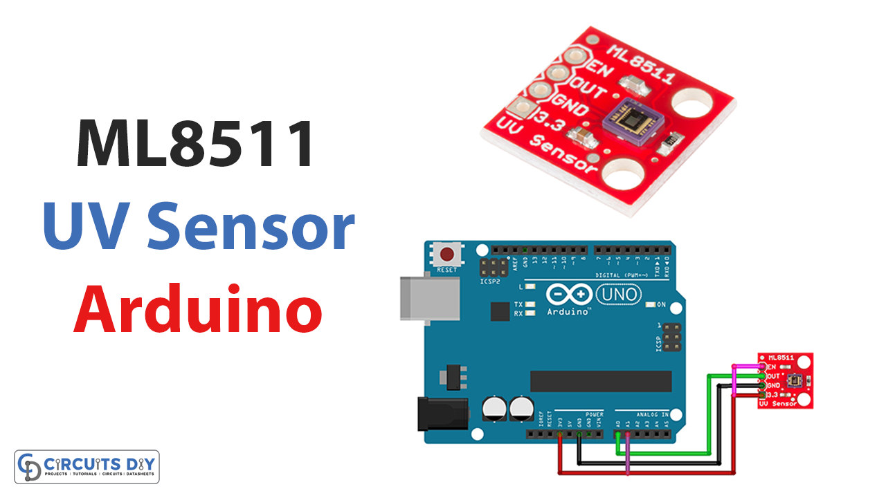
ML8511 UV Sensor Module with Arduino
Once you get the required components, here are the steps for interfacing the ML8511 UV sensor module with Arduino:
Schematic
Make connections according to the circuit diagram given below.
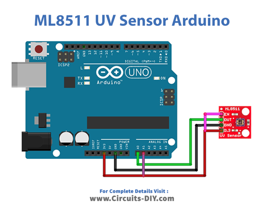
Wiring / Connections
| Arduino | ML8511 UV Sensor |
|---|---|
| 3.3V,A1 | VCC, EN |
| GND | GND |
| A0 | Out |
Code
Now copy the following code and upload it to Arduino IDE Software.
//pin definitions
int UV_OUT = A0;    //Sensor Output
int REF_3V3 = A1;   //3.3V power on the Arduino board

void setup()
{
  Serial.begin(9600);
  Serial.println("ML8511 example");
}

void loop()
{
  int uv_Level = analogRead_average(UV_OUT);
  int ref_Level = analogRead_average(REF_3V3);

  //Use the 3.3V power pin as a reference to get a very accurate output value from sensor
  float output_Voltage = 3.3 / ref_Level * uv_Level;

  float uvIntensity = mapfloat(output_Voltage, 0.99, 2.8, 0.0, 15.0); //Convert the voltage to a UV intensity level -numbers from datasheet-

  Serial.print("ML8511 output: ");
  Serial.print(uv_Level);

  Serial.print(" / ML8511 voltage: ");
  Serial.print(output_Voltage);

  Serial.print(" / UV Intensity (mW/cm^2): ");
  Serial.print(uvIntensity);

  Serial.println();

  delay(500);
}

//Takes an average of readings on a given pin
//Returns the average
int analogRead_average(int pinToRead)
{
  int NumberOfSamples = 8;
  int runningValue = 0;

  for(int x = 0; x < NumberOfSamples; x++)
    runningValue += analogRead(pinToRead);
  runningValue /= NumberOfSamples;

  return(runningValue);
}

//The Arduino Map function but for floats
//From: http://forum.arduino.cc/index.php?topic=3922.0
float mapfloat(float x, float in_min, float in_max, float out_min, float out_max)
{
  return (x - in_min) * (out_max - out_min) / (in_max - in_min) + out_min;
}
Let’s Test It
It’s now time to test the circuit! Open the serial monitor in the Arduino IDE. You should see the UV intensity data being printed to the serial monitor every second. Now that you’re able to read the UV intensity data from the sensor, you can use it to trigger all sorts of fun projects and applications.
Working Explanation
- The code is used to read the UV intensity data from the ML8511 sensor module.
- The code begins by defining the pins connected to the sensor and references 3.3V power and setting up serial communication in the void setup function.
- The code reads the raw analog data from the UV sensor using the analogRead_average function in the void loop function. It then calculates the output voltage. Finally, it converts the output voltage to a UV intensity level using the mapfloat function and prints the raw analog data, output voltage, and UV intensity level to the serial monitor.
- The analogRead_average function is used to take multiple readings from the specified pin and return the average value, which can help improve the readings’ accuracy. The mapfloat function scales the output voltage to the UV intensity level based on the minimum and maximum values specified in the function arguments.
- This code can be modified to fit the specific needs of your project, such as using the UV intensity data to trigger an action or displaying the data in a particular way.
Applications
- Smartphones
- Watches
- Weather stations, etc
Conclusion.
We hope you have found this Interfacing ML8511 UV Sensor Module with Arduino Circuit very useful. If you feel any difficulty in making it feel free to ask anything in the comment section.