Introduction
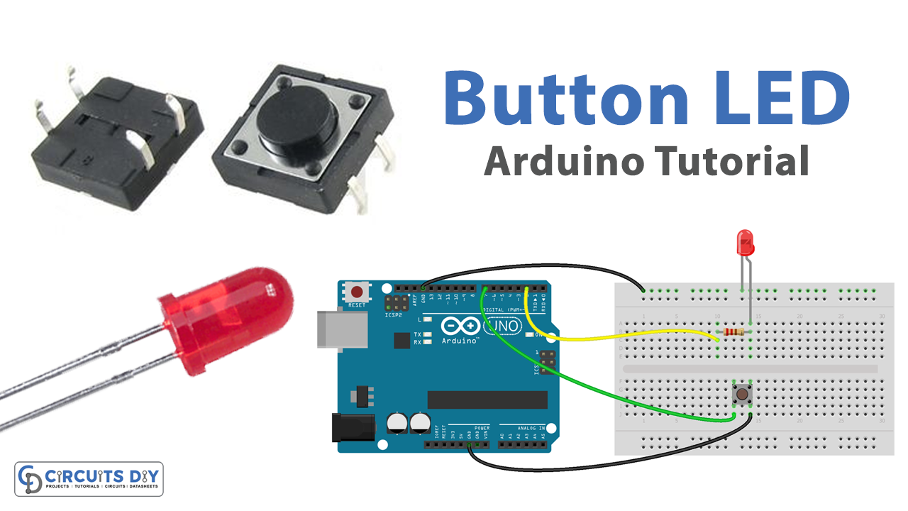
Controlling an LED using a pushbutton is a basic yet powerful concept in the world of electronics and microcontroller programming. It demonstrates the capability of a microcontroller to read digital inputs and control digital outputs. By using an Arduino Uno microcontroller, a simple pushbutton, and an LED, we can create a circuit that allows us to turn on and off an LED by pressing a button.
The ability to control devices such as LEDs, motors, sensors, and other electronic components is the foundation of many electronic projects, and understanding the basics of this concept is essential for anyone interested in learning about electronics and MCU programming. In this tutorial, we will explore the steps and the code needed to control an LED using a pushbutton with an Arduino Uno microcontroller.
Hardware Components
You will require the following hardware for the Button with LED Tutorial.
| S.no | Component | Value | Qty |
|---|---|---|---|
| 1. | Arduino UNO | – | 1 |
| 2. | USB Cable Type A to B | – | 1 |
| 3. | Button | – | 1 |
| 4. | Power Adapter for Arduino | 9V | 1 |
| 5. | LED | – | 1 |
| 6. | Resistor | 220Ω | 1 |
| 7. | Breadboard | – | 1 |
| 8. | Jumper Wires | – | 1 |
Button with LED
- Connect one side of the pushbutton to a digital input pin on the Arduino board (e.g. pin 2)
- Connect the other side of the pushbutton to ground
- Connect one side of the LED to a digital output pin on the Arduino board (e.g. pin 13)
- Connect the other side of the LED to a resistor (e.g. 220 ohms)
- Connect the other side of the resistor to ground
- In the Arduino sketch, use the
pinMode()function in thesetup()function to configure the input and output pins:
void setup() {
  pinMode(2, INPUT);
  pinMode(13, OUTPUT);
}
- In the
loop()function, use thedigitalRead()function to read the state of the input pin (HIGH or LOW) and store the value in a variable:
void loop() {
  int buttonState = digitalRead(2);
- Use an if-else statement to check the state of the input pin and turn the LED on or off:
if (buttonState == HIGH) {
    digitalWrite(13, HIGH);
  } else {
    digitalWrite(13, LOW);
  }
- To display the status of the LED in the serial monitor, use the
Serial.begin()function in thesetup()function to initialize the serial communication and set the baud rate:
void setup() {
  Serial.begin(9600);
  pinMode(2, INPUT);
  pinMode(13, OUTPUT);
}
- In the
loop()function, use theSerial.print()function to send the state of the LED to the serial monitor:
void loop() {
  int buttonState = digitalRead(2);

  if (buttonState == HIGH) {
    digitalWrite(13, HIGH);
    Serial.print("LED is on");
  } else {
    digitalWrite(13, LOW);
    Serial.print("LED is off");
  }
}
- Upload the sketch to the Arduino board and open the serial monitor to see the status of the LED.
It should be noted that you can use any pin number for the pushbutton and LED, but make sure that you are using the correct pin number in the sketch. Also, the baud rate can be changed as per requirement.
Schematic
Make connections according to the circuit diagram given below.

Wiring / Connections
| Arduino | LED | Button |
|---|---|---|
| D3 | +ve with resistor | |
| GND | GND | PIN2 |
| D7 | PIN1 |
Installing Arduino IDE
First, you need to install Arduino IDE Software from its official website Arduino. Here is a simple step-by-step guide on “How to install Arduino IDE“.
Code
Now copy the following code and upload it to Arduino IDE Software.
const int BUTTON_PIN = 7;  // the number of the pushbutton pin
const int LED_PIN =  3;   // the number of the LED pin

// variables will change:
int buttonState = 0;   // variable for reading the pushbutton status

void setup() {
  // initialize the LED pin as an output:
  pinMode(LED_PIN, OUTPUT);
  // initialize the pushbutton pin as an pull-up input:
  // the pull-up input pin will be HIGH when the switch is open and LOW when the switch is closed.
  pinMode(BUTTON_PIN, INPUT_PULLUP);
}

void loop() {
  // read the state of the pushbutton value:
  buttonState = digitalRead(BUTTON_PIN);

  // control LED according to the state of button
  if(buttonState == LOW)         // If button is pressing
    digitalWrite(LED_PIN, HIGH); // turn on LED
  else                           // otherwise, button is not pressing
    digitalWrite(LED_PIN, LOW);  // turn off LED
}
Working Explanation
The code starts by defining the pin number of the pushbutton and the LED. Then, in the setup() function, the pinMode() function is used to configure the input and output pins. The pinMode(2, INPUT) sets the pin 2 as an input pin, and pinMode(13, OUTPUT) sets the pin 13 as an output pin. It also starts the serial communication by calling Serial.begin(9600).
The loop() function is executed repeatedly. In the loop, the digitalRead() function is used to read the state of the pushbutton and stores it in a variable called buttonState. The digitalRead(2) reads the state of pin 2, whether it’s high or low, and assigns it to buttonState. After that, an if-else statement is used to check the state of the pushbutton. If the pushbutton is pressed (buttonState == HIGH), the LED is turned on by calling digitalWrite(13, HIGH). If the pushbutton is not pressed, the LED is turned off by calling digitalWrite(13, LOW). Finally, the code uses the Serial.print() function to send the state of the LED to the serial monitor.
Conclusion.
We hope you have found this Arduino – Button LED Circuit very useful. If you feel any difficulty in making it feel free to ask anything in the comment section.