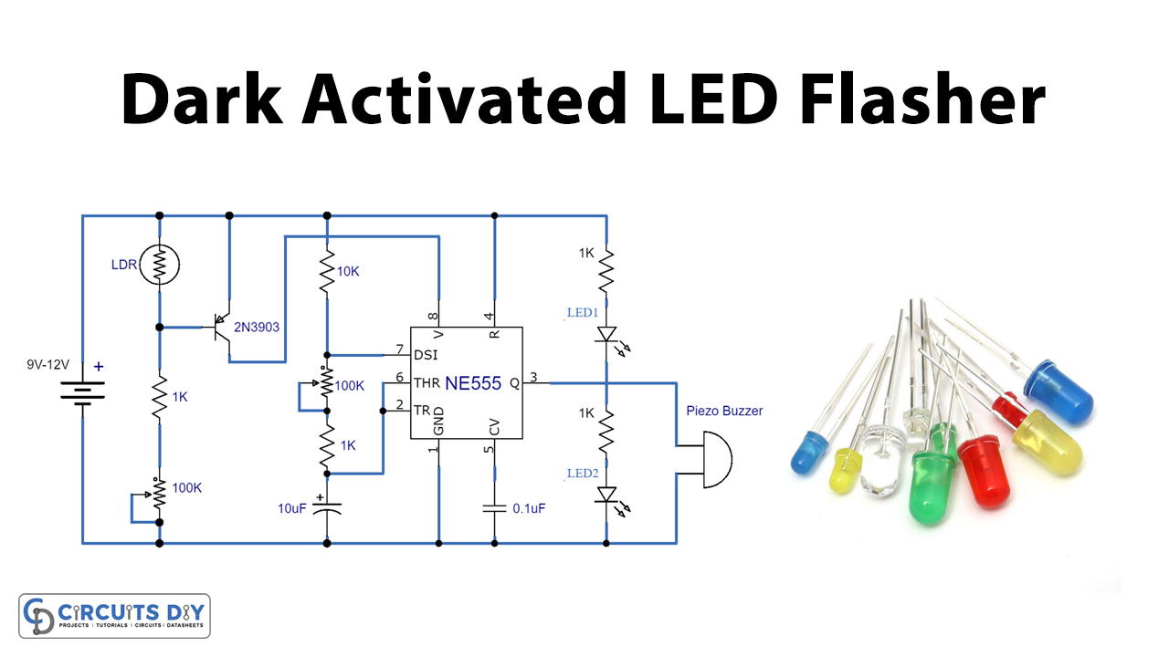
In this tutorial, we are going to make an interesting DIY project of the Dark Activated LED Flasher circuit. When there is no light on the surface of the LDR the circuit will flash two LEDs in flip flop manner. The IC that we are using is a 555-timer IC. We have used a piezo buzzer in this circuit which is optional. It provides a beep signal with the blinking of the LED2. If you want to blink a single LED then you can remove LED1 and the resistor connected with it.
You can also use a relay switch instead of a piezo buzzer. In that way, you can connect any AC/DC appliance light lamps, fans, etc., and operate them with this circuit.
Hardware Components
The following components are required to make Dark Activated LED Circuit
| S.no | Component | Value | Qty |
|---|---|---|---|
| 1. | Breadboard | – | 1 |
| 2. | Electrolytic Capacitor | 10µF | 1 |
| 3. | Ceramic Capacitor | 0.01µF | 1 |
| 4. | IC | NE555 Timer | 1 |
| 5. | LED | – | 2 |
| 6. | Transistor | 2N3904 | 1 |
| 7. | LDR | – | 1 |
| 8. | Piezo Buzzer | – | 1 |
| 9. | Resistors | 1K, 10K | 4, 1 |
| 10. | Variable Resistor | 100K | 2 |
| 11. | Battery | 9-12V | 1,1 |
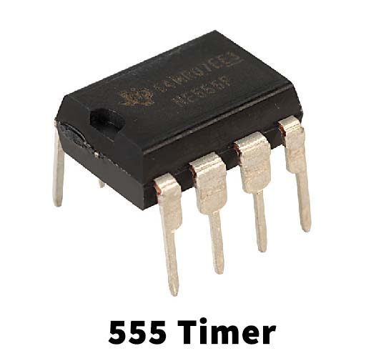
555 IC Pinout

For a detailed description of pinout, dimension features, and specifications download the datasheet of 555 Timer
2N3904 Pinout
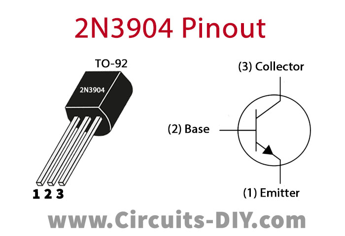
For a detailed description of pinout, dimension features, and specifications download the datasheet of 2N3904
Dark Activated LED Circuit

Working Explanation
The operating voltage of this circuit is 9-12V DC. A 100K variable resistor R2 is used to adjust the sensitivity of LDR. In the dark LDR’s resistance will be maximized and the transistor will start conducting giving an input signal to the 555 timer IC. Another variable resistor of 100K R4 is used to adjust the frequency of the pulses generated from 555 timer IC which controls the flashing speed of LEDs. The output pulses of this IC will provide power to the LEDs and they will flash in a flip-flop manner.
Circuit alternatives:
This circuit can be operated on low voltages like 5 or 6 volts. If you’re working with 5-6V then replace the resistors R6 and R7 by 390 ohms or if you’re planning on using a relay at this circuit’s output instead of a piezo buzzer then used the relay of the same value as the operating voltage.
Applications and Uses
- Sirens
- Timer Switch
- Warning Devices
- Safety Blinkers
- Toys