What is PWM?
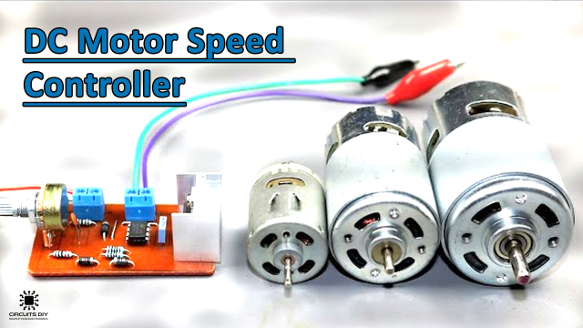
PWM (Pulse Width Modulation) is an important feature of today’s microcontroller due to its requirement for controlling many devices in every field of Electronics almost. PWM is widely used for motor control, lighting control, etc. Sometimes we do not require a microcontroller in our applications and if we need to generate a PWM without a microcontroller then we prefer some general-purpose ICs like op-amp, timers, pulse generators, etc. So in this tutorial, we are going to make a “PWM Generation Circuit using 555 precision timer IC”
The core of this circuit is a NE555 precision Timer IC. The IC possesses an oscillation frequency ranging from 670 to 680 Hz. Here, this NE555 timer functions in astable multivibrator mode An astable multivibrator is a free-running oscillator that switches continuously between its two unstable states. With no external signal applied, the transistors alternately switch from cutoff to saturation state at a frequency that RC time constants of the coupling circuit determine. If these time constants are equal (R and C are equal) then a square wave will generate with a frequency of 1/1.4 RxC. Hence, an astable multivibrator is also a pulse generator or a square wave generator, which corresponds perfectly with the requirement of Pulse width modulation (PWM).
Hardware Components
The following components are required to make PWM Circuit
| S. No | Component | Value | Qty |
|---|---|---|---|
| 1) | IC | NE555 Timer | 1 |
| 2) | Potentiometer | 10K | 1 |
| 3) | LEDs | 3mm, red | 1 |
| 4) | Multimeter | – | 1 |
| 5) | Oscilloscope | – | 1 |
| 6) | Electrolytic Capacitor | 0.1uF | 1 |
| 7) | Resistors | 1K, 100Ohm | 2 |
| 8) | DC Battery | 9V | 1 |
| 9) | Battery Clips | – | 1 |
| 10) | Breadboard | – | 1 |
| 11) | Connecting Wires | – | As per need |
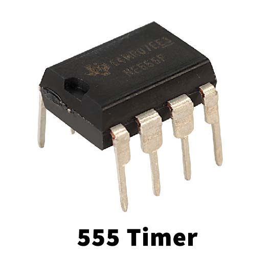
555 Timer Pinout

For a detailed description of pinout, dimension features, and specifications download the datasheet of 555 Timer
PWM Circuit Diagram

Working Explanation
The 555 timers’ astable arrangement creates a square wave with time high and time low. The ratio of these times can be varied by changing R1, R2, and C1. Here, In this circuit, we are controlling the output frequency of the PWM signal using a 10K pot & 100nF capacitor.
Here, we have used a 10K pot in place of a fixed resistor, so as to change the duty cycle of the output signal. C1 Capacitor (100nF) charging through diode D1 and discharging through diode D2 will generate a PWM signal at the 555 timer’s output pin.
Applications
- PWM is used in telecommunications for encoding purposes.
- It is also used for applications such as controlling DC motors, valves, pumps, hydraulics, and other mechanical parts.
- Computer Motherboards require PWM Signals that control the heat generated on the board. A 4 Pin PWM header is embedded in the fan that helps to dissipate the heat from the motherboard.