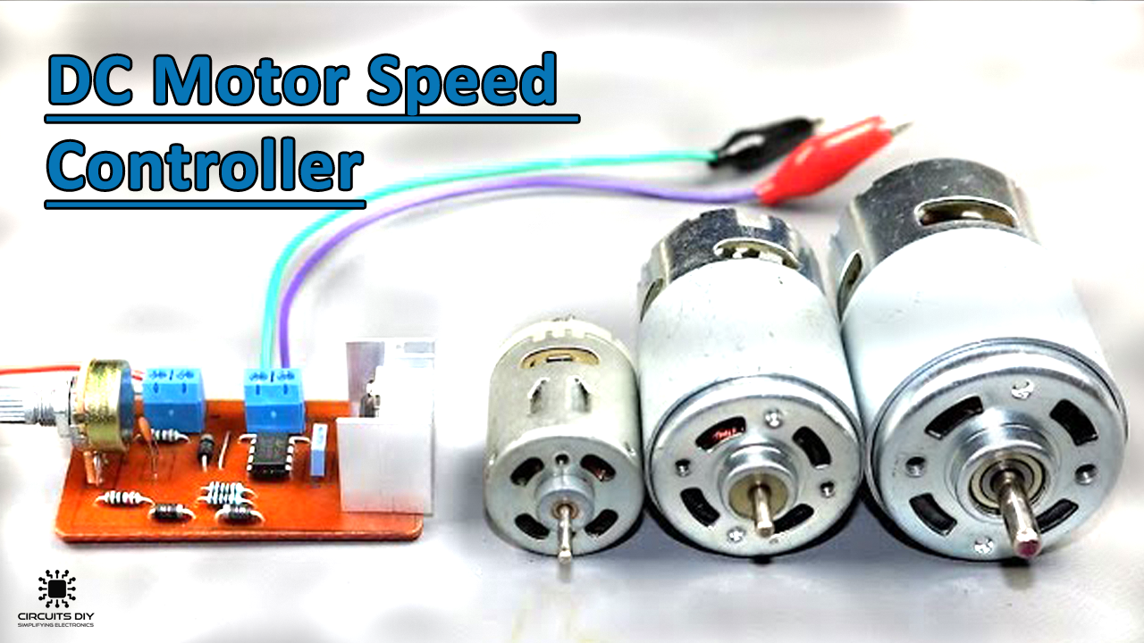
What is a DC Motor Speed Controller?
A DC motor speed controller is a simple electronic circuit that is used to linearly control the speed of a connected DC Drive/Motor by simply rotating an attached potentiometer. DC Motor speed control can be achieved by a wide array of electronic configurations. In this article, we will be focusing on How To Make A DC Motor Speed Controller using the pulse width modulation (PWM) technique. Controlling a DC motor using PWM has an inherent advantage that the power loss in the switching transistor is always small due to the transistor being either fully “ON” or fully “OFF”. As a result, the switching transistor has a reduced power dissipation giving it a linear type of control which results in better speed stability. Another advantage is that the motor can be rotated much more slowly without stalling. As the amplitude of the motor always remains constant
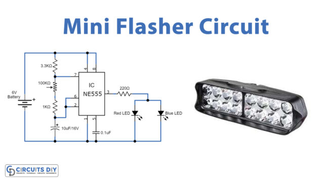
The heart of this circuit is a NE555 precision timer IC. The 555 timer IC possesses an oscillation frequency ranging from 670 to 680Hz. Here, the NE555 timer IC is running in an astable mode in order to generate a free-running PWM square wave signal.
JLCPCB is the foremost PCB prototype & manufacturing company in china, providing us with the best service we have ever experienced regarding (Quality, Price Service & Time).
Hardware Components
The following components are required to make DC Motor Speed Controller Circuit
| S.no | Component | Value | Qty |
|---|---|---|---|
| 1. | DC Motor | 12V/6000 – 10000RPM | 1 |
| 2. | IC | NE555 Timer | 1 |
| 3. | Power MOSFET | P75NF75 | 1 |
| 4. | Potentiometer | 100K | 1 |
| 5. | Diodes | 1N4007 | 3 |
| 6. | Capacitors | 100nF, 1nF | 2 |
| 7. | Resistor | 10K, 1K | 4 |
| 8. | Terminal Block Connectors | – | 2 |
| 9. | Soldering Iron | 45W – 65W | 1 |
| 10. | Soldering Wire with Flux | – | 1 |
| 11. | DC Battery | 12V | 1 |
| 12. | Veroboard/PCB Board | – | 1 |
| 13. | Battery Clips | – | 1 |
| 14. | Jumper Wires | – | As per need |
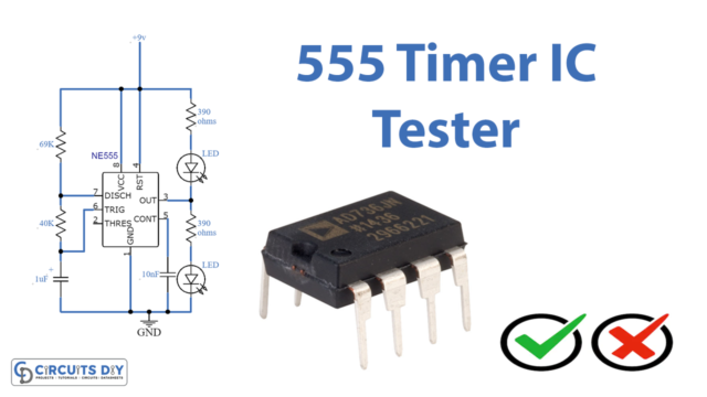
555 Timer Pinout
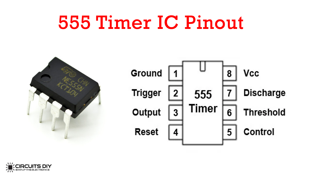
For a detailed description of pinout, dimension features, and specifications download the datasheet of 555 Timer
Useful Steps
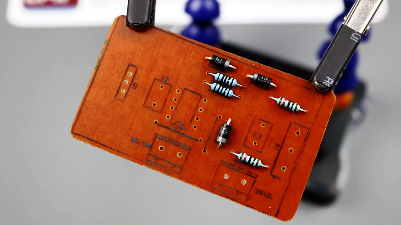
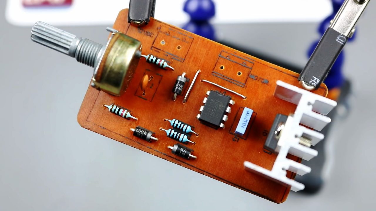
1) Solder down all the resistors
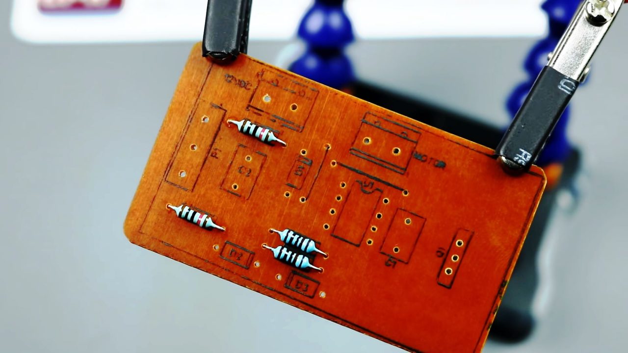
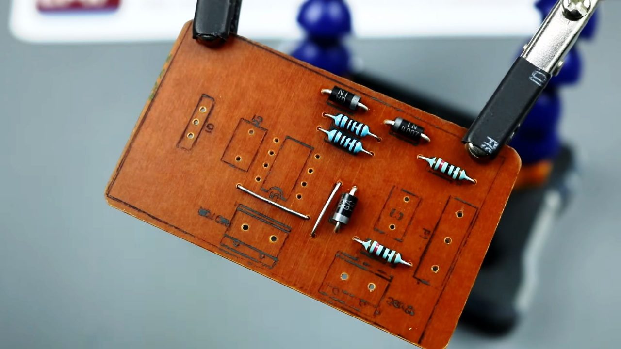
2) After that, solder all the diodes on the Veroboard/PCB board.
3) Now, Solder all the required jumper wires.
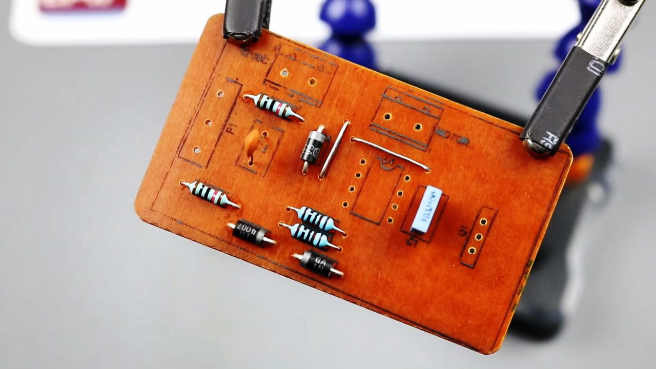
4) After that, solder the capacitors on the Veroboard.
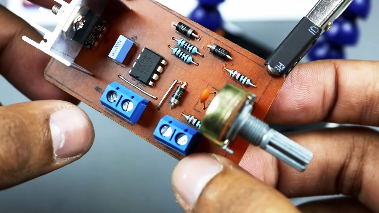
5) Solder the 555 Timer IC & the 100K pot on the Veroboard.
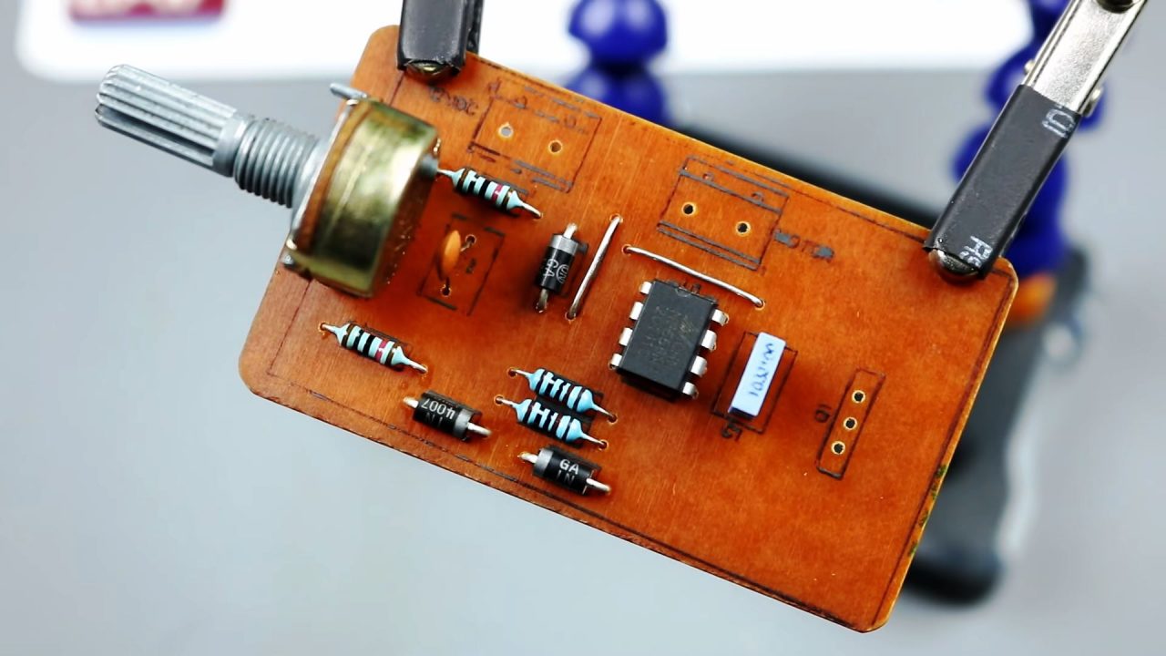
6) Solder the switching power MOSFET P75NF75 on the Veroboard.
7) Solder the 12V DC input block connectors & the DC motor Output block connectors.
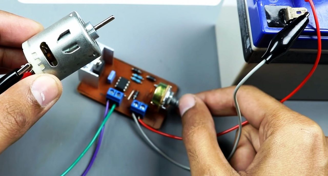
8) Now power up & test the circuit using a 12V DC Battery.
Working Explanation
The working of this circuit is quite simple to follow. Here, a free running square wave signal (PWM) is used to control the speed of a DC motor, this PWM signal is generated by operating a NE555 timer IC in astable multivibrator mode. The 100K preset Pot controls the active time of the output PWM signal. The average output voltage to the DC motor depends upon the duty cycle of the PWM signal.
The PWM output pulses from the timer IC serve as a controls signal to the gate terminal of the P75NF75 Power MOSFET. The MOSFET then reacts and controls the connected DC motor in response to the setting of the 100K Preset Pot. This allows the MOSFET to drive the DC motor at a high current.
Applications
- Used in applications such as conveyor belts & escalators in order to eliminate power losses when the system is in an idle state.
- Also used in devices such as pumps and blowers to control flow and energy.