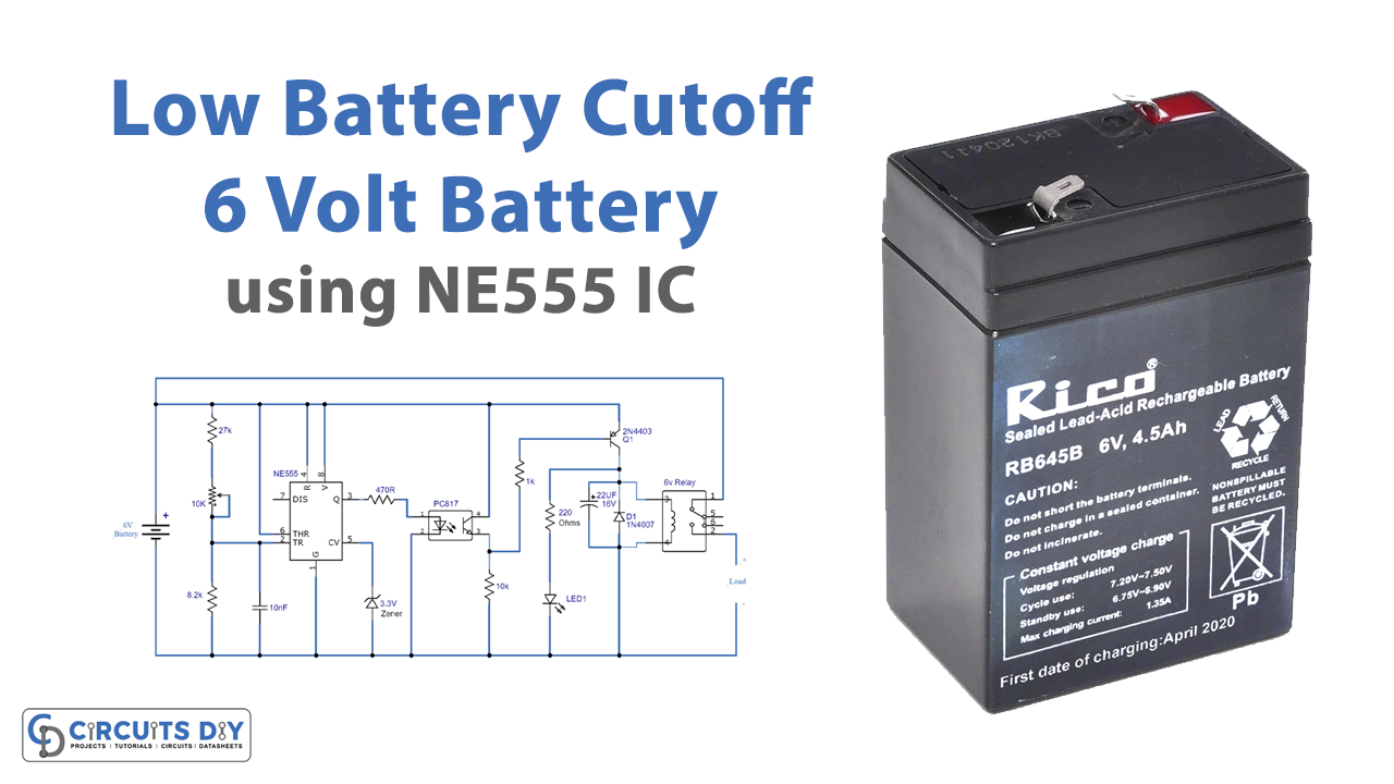
In this article, we are making a project on Low Battery Cutoff For 6V Batteries Using 555 IC. This circuit will disconnect the battery when its voltage falls below 6V, this will save the battery from getting deep discharged. Deep discharging or complete discharging can be an issue with rechargeable batteries, it affects their durability. With the help of this circuit, the battery can be saved from harming its life span.

Hardware Components
The following components are required to make Low Battery Cutoff Circuit
| S.no | Component | Value | Qty |
|---|---|---|---|
| 1. | Battery | 6V | 1 |
| 2. | Phototransistor | PC817 | 1 |
| 3. | IC | NE555 Timer | 1 |
| 4. | Zener diode | 3.3V | 1 |
| 5. | Transistor | 2N4403 | 1 |
| 6. | Relay | 6V | 1 |
| 7. | Diode | 1N4007 | 1 |
| 8. | Resistor | 27K, 470R, 8.2K, 10K, 1K, 220Ω | 1, 1, 1, 1, 1, 1 |
| 9. | Variable Resistor | 10K | 1 |
| 10. | Ceramic Capacitor | 10nF | 1 |
| 11. | LED | – | 1 |
| 12. | Electrolytic Capacitor | 22uF/16V | 1 |
NE555 IC Pinout

For a detailed description of pinout, dimension features, and specifications download the datasheet of 555 Timer
2N4403 Pinout
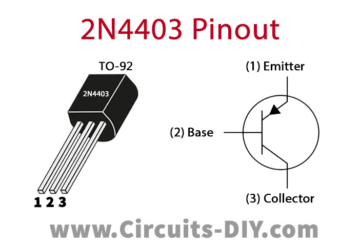
For a detailed description of pinout, dimension features, and specifications download the datasheet of 2N4403
Low Battery Cutoff Circuit
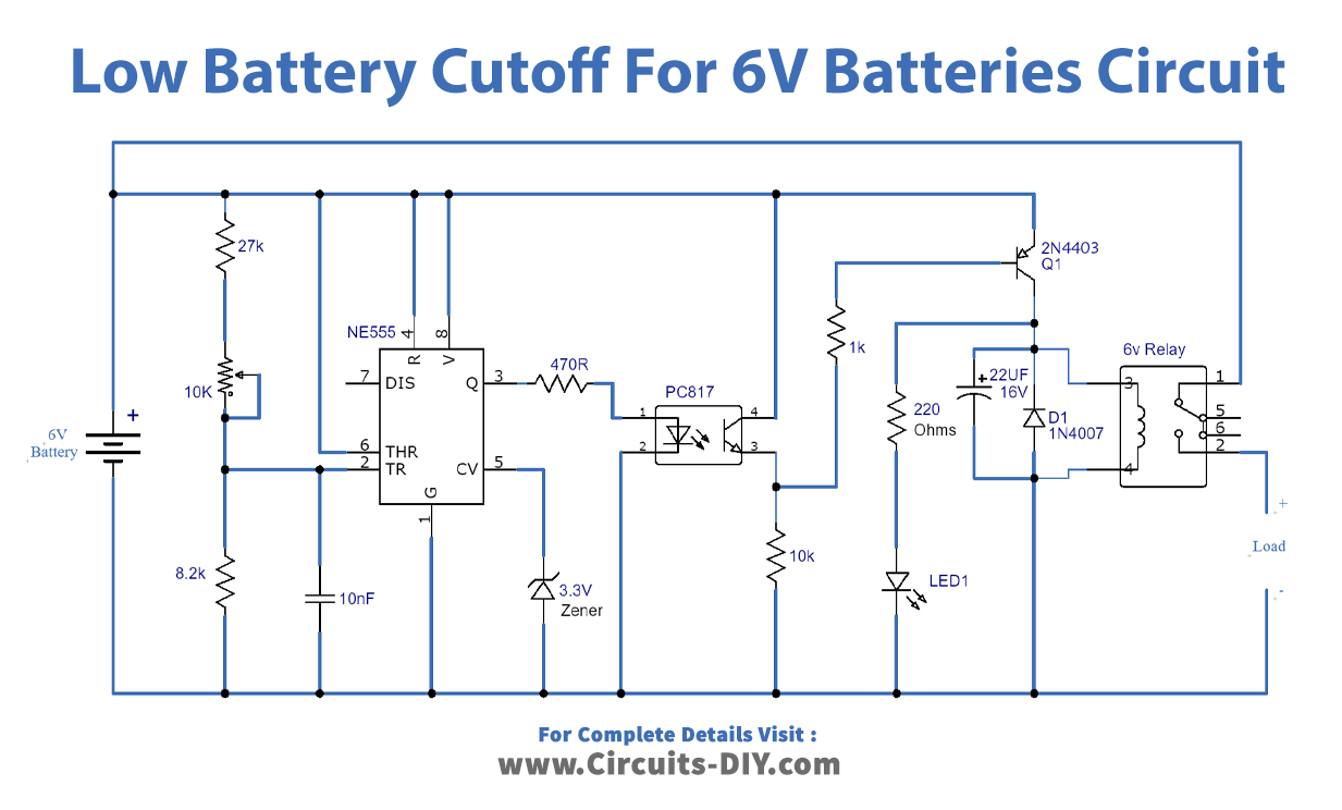
Working Explanation
The 555 timer IC is working as a comparator to detect the voltage of the battery. When it is less than 6V the IC will give an output that will deactivate the LED indicating the battery is low. The relay will be deactivated as well which will disconnect any load that was connected with the battery and saves it from getting deep or completely discharged.
Circuit Adjustments
After building this circuit and before using it you have to calibrate it by following these steps.
- Take a variable power supply and set its voltage to 5.9V.
- Replace the battery in the circuit with this variable power supply.
- Adjust the variable resistor until LED and the relay deactivates
- Increase the voltage of the variable power supply to 6-6.5V, at this point the LED and the Relay should turn back ON.
- Again, set the voltage of the variable power supply to 5.9V, and the LED and relay should be deactivated.
- Now your calibration is done and the circuit is ready to use. Put a fully charged 6V battery back into the circuit and remove the variable power supply.
Applications and uses
This circuit can be used with all Sealed lead acid or lead-acid batteries with 6V.