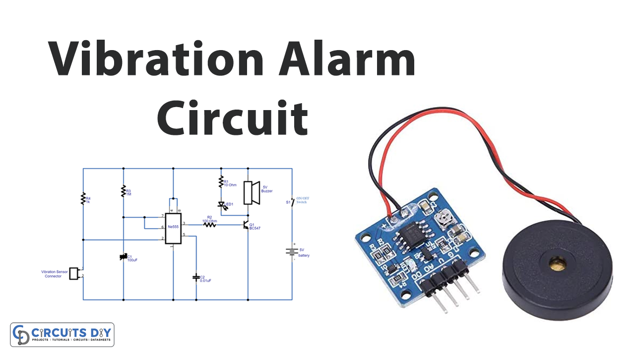
In this tutorial, we are going to make a “Vibration alarm circuit using ic 555”. The versatile astable multivibrator configuration of IC 555 allows us, to implement it for making various types of sirens and alarm circuits. This becomes possible because an astable is basically a waveform generator, and can be customized for generating different types of sound waveforms, resembling alarm and siren sounds.
Here we design a simple and reliable vibration alarm circuit by using a vibration sensor switch SW – 18020P with timer IC555 and a few easily available components. The SW – 18020P sensor has two terminals and there is no contact between terminals in idle conditions. When vibration or external force is applied to the sensor two contact pins of the sensor are closed. This sensor is suitable for producing trigger signals to the timer ICs and as well as microcontrollers.
Vibration Sensor SW – 18020P
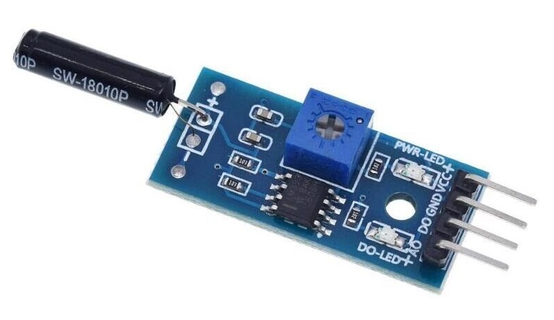
According to the physical view of the vibration sensor SW – 18020P and the internal view. This sensor works in the maximum voltage range of 12V and has a maximum current value of < 5mA. It creates < 10MΩ during the idle condition (no vibration detected) and produces < 5Ω during vibration detection. It has a fast response time of 2ms and has an ambient temperature range of < 100°C. It is suitable for different applications that need vibration detection. In normal the lifespan can be reached at 200,000 cycles. It doesn’t have a direction, normally it’s an open circuit inside. And it turns to close when it is shacked instantly, and then turns to open again when the motion is gone.
Hardware Required
| S.no | Component | Value | Qty |
|---|---|---|---|
| 1. | Vibration Sensor | SW–18020P | 1 |
| 2. | Transistor | BC547 | 1 |
| 3. | IC | NE555 Timer | 1 |
| 4. | Buzzer | 5V | 1 |
| 5. | Switch | – | 1 |
| 6. | Resistor | 1KΩ,1MΩ,100Ω,10Ω | 1,1,1,1 |
| 7. | Capacitor | 100uf,0.01uf | 1,1 |
| 8. | Connecting Wires | – | – |
| 9. | LED | – | 1 |
| 10. | Battery | 5V | 1 |
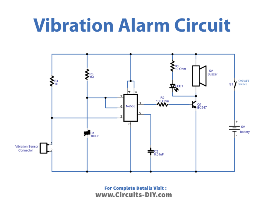
Circuit Diagram
Working Explanation
As we have used the SW-18020 sensor, it is a non-direction vibration-induced trigger switch that can be triggered at any angle. At the rest, it is an open circuit “OFF-state”. When the external force touches and reaches the corresponding vibration, or moves in speed to reach the adequate centrifugal force. The conductive feet will be conducted instantaneously “ON-State”. When the external force disappears, the switches will revert to the “OFF-State”. Different model has different sensitivity. This circuit has timer IC 555 configured in monostable mode. It produces a buzzer sound and light indication for up to two minutes during the vibration detection. You can change this alarm sound duration by changing the timer elements R3 and C2.
T = 1.1 * R * C
for given circuit
Tmono = 1.1 * R3 * C2
= 1.1 * 1MΩ * 100µF
= 1.1 * 1000000 * 0.0001
Tmono = 110 Seconds.
When the vibration is detected by the sensor, it will produce a trigger signal. And it triggers the timer IC 555, hence it produces a mono-timing pulse up to 110 Sec. The output pulse taken from pin 3 is applied to the NPN transistor BC547, here the Q1 reacts as a switching device and makes contact between buzzers, and LED to ground supply. It lasts up to the mono pulse end. So the buzzer produces an alarm sound. If the circuit deserves a fixed place means you can connect a +5V DC adapter to the alarm circuit.
Applications
- Automotive devices
- Home electrical devices
- Automatic power-off function for household appliances
- Air condition / Air warm blower fall prevention protection switches
- Communication devices
- Toys