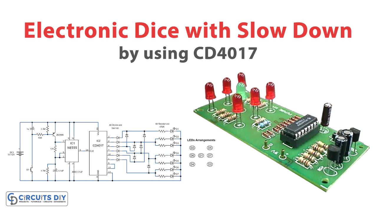
Does your DICE at any point tumble off the table after you moved it when playing a board game? Indeed? Say no more to rolling DICE. In this tutorial, we will demonstrate to you how to make electronic DICE with the well-known incorporated circuit component 555 clock and 4017 Johnson decade counter. This task includes building your own electronic DICE. You can utilize it in place of a customary one. By using a switch, you can turn the battery ON. After that, you press the contact Switch to ‘toss’ the dice. A portion of the LEDs will illuminate.
The LEDs are fundamentally the spots on the dice. The number of LEDs that light up is erratic and unpredictable. This electronic dice circuit has an extra slow-down function; this is a fascinating feature that gives all the fulfilling outcomes. In the wake of squeezing the press button S1, the LEDs will begin blazing in speed, this speed will diminish gradually, and lastly, stop on a single unpredictable result.
Hardware Components
The following components are required to make an Electronic Dice Circuit
| S.no | Component | Value | Qty |
|---|---|---|---|
| 1. | IC | NE555 timer | 1 |
| 2. | IC | CD4017 | 1 |
| 3. | PNP transistor | 2N3906 | 1 |
| 4. | Power diodes | 1N4148 | 12 |
| 5. | Capacitor | 1µF, 0.1µF, 0.01µF | 1, 1, 1 |
| 6. | Resistor | 10KΩ, 3.3MΩ, 4.7MΩ, 10MΩ | 1, 1, 1, 1 |
| 7. | Variable resistors | 470R | 7 |
| 8. | LED | – | 7 |
| 9. | Switch | – | 1 |
| 10. | Battery | 9V – 12V | 1 |
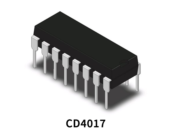
CD4017 Pinout
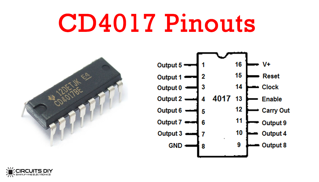
For a detailed description of pinout, dimension features, and specifications download the datasheet of CD4017
NE555 IC Pinout

For a detailed description of pinout, dimension features, and specifications download the datasheet of NE555
Electronic Dice Circuit

Working Explanation
The circuit is isolated in two sections, the initial segment of the circuit works around a 555 clock IC which gives clock pulses on the clock input of the 4017-decade counter IC. The subsequent part works around a 4017 IC which actuates a new output and shuts the last one when a pulse receives on its clock input pin 14. Currently, we utilize just 6 outputs of the 4017 IC.
At the point when the press button S1 squeezes the 1uF capacitor charges and the S1 is released, the 2N3904 transistor turns ON and the 555 clock IC starts to generate pulses to its output pin 3, these pulses are step by step diminished as the 1uF capacitor discharges. At the point when the 1uF capacitor turns out to be completely discharged the transistor turns OFF and the 555 clocks quit giving clock pulses to the clock input pin of the 4017 counter, because of which the decade counter stops on any one output.
The working voltage of the circuit is 9V to 12V DC. For good execution, place the circuit in an appropriate enclosure, and place the press button S1 and the LEDs output side of the crate.
Applications and Uses
- It is used to play numerous games like Snake Ladder, Ludo, and so forth.
- A Digital dice is a decent option for antiquated dice, It works such fast that nobody can cheat.
- The Kit utilizes 7 light transmitting diodes (LEDs) to reenact the rolling of a die. It has a slowdown feature so you can see the rolling, gradually slow down, and afterward stop.