In this tutorial, we are going to show you how to make a Time delay relay circuit using a 555 timer IC. This circuit is able to trigger the relay from a few seconds to a few minutes after pushing the Switch S1. It is easy to make and uses only a few components.
A relay is a switch that is operated electrically between two terminals that are, normally closed and normally open. This depends on the energizing and de-energizing of the coil in the relay. There are some relays in which the switching process is not immediate and takes time, they provide a “time delay” between the energizing and the de-energizing of the coil. These relays are called Time Delay Relays that we are going to use today.
The main difference between these relays is that normal relays switch from a normally close terminal to a normally open terminal immediately whereas in time delay relays the contacts are closed or open only after a preset time interval.

Hardware Components
The following components are required to make Time Delay Relay Circuit
| S.no | Component | Value | Qty |
|---|---|---|---|
| 1. | DC Supply | 9V-12V | 1 |
| 2. | Switch | – | 1 |
| 3. | IC | NE555 Timer | 1 |
| 4. | Resistor | 1M, 470 ohms | 1, 1 |
| 5. | Ceramic Capacitor | 100uF | 1 |
| 6. | Relay | 12V | 1 |
| 7. | Diode | 1N4007 | 1 |
| 8. | LED | 5mm | 1 |
| 9. | Breadboard | – |
555 IC Pinout

For a detailed description of pinout, dimension features, and specifications download the datasheet of 555 Timer
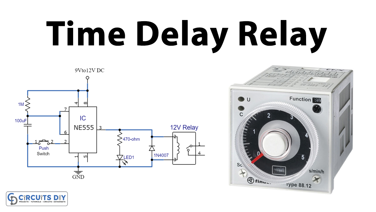
Time Delay Relay Circuit
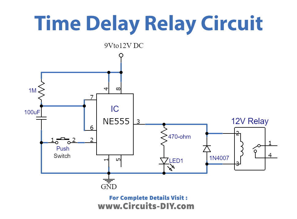
Working Explanation
The operating voltage of this circuit is 9-12V DC. We are using an electrolytic capacitor of 1000uF which is responsible for setting the time delay of approximately 2 minutes. Time delay can be increased by increasing the value of the capacitor. For example, a 220uF capacitor will give you a delay of approx. 5 minutes.
A switch is used at the input pin of the 555 timer IC along with a capacitor, when we will turn the switch ON relay will be activated and will provide the time delay.
In this circuit, we are also using an LED with a 470 ohms resistor to indicate whether the relay is in an ON state or OFF. Using LED and the resistor is completely optional, you can skip this step if you want to make this circuit even simpler.
Application and Uses
- Protection of sensitive electronic devices from spikes and surges
- Flashing light control
- Motor soft-start delay control