Introduction
Switches are our daily life, from our home appliances to other electrical machines, turning ON the switches is the only way to turn ON the machines. Thus, switches are of different types, usually, mechanical switches are used regularly. Touch switches were not very regularly used but nowadays, they are replacing different other switches. Maybe because they have an advantage over mechanical switches. And, maybe because they can be utilized in today’s technology. For example, in mobile phones, tablets, etc. So, in this tutorial, we are going to the “Simple Touch Switch circuit”.
If you use other switches, you need to press the button hard enough so the upper conductive follow comes into contact with the base conductive follow. With a touch switch, you just need to contact the button with an exposed finger

Hardware Components
The following components are required to make the Touch Switch Circuit
| S.no | Component | Value | Qty |
|---|---|---|---|
| 1. | Touch plate (refer to text) | – | 1 |
| 2. | IC | NE555 Timer | 1 |
| 3. | LED | – | 1 |
| 4. | Capacitor | 10uF/25V, 0.01uF | 1,1 |
| 5. | Resistor | 100KΩ, 470Ω | 1,1 |
| 6. | Connecting wires | – | – |
| 7. | Battery | 6V | 1 |
| 8. | Connector | 2-Pin | 1 |
NE555 IC Pinout

For a detailed description of pinout, dimension features, and specifications download the datasheet of 555 Timer
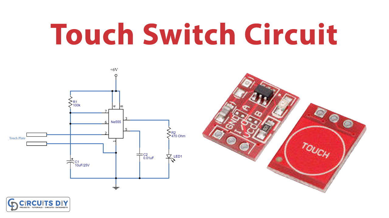
Touch Switch Circuit
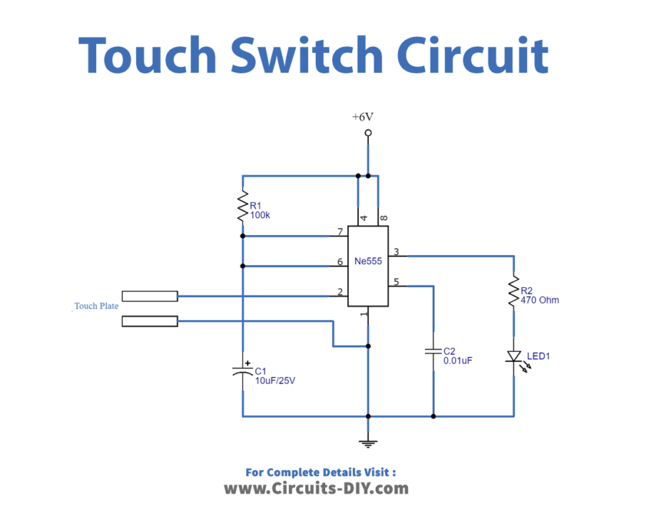
Working Explanation
In this Simple Touch Switch Circuit, the NE555 IC is working as a monostable multivibrator to generate pulses. There is a touch plate that senses human contact. When you place your finger on that touch plate, the trigger pin of an IC receives the signal and generates the mono pulse at the output side. Know that the pulse depends on the timing capacitor c1 and resistor R1. At the output side LED is connected which turns On after receiving the pulse. You can connect any other load at the output.
Application and Uses
- To drive different appliances.
- Automation systems.
- Electronic gadgets.