In this DIY tutorial, we will discuss a simple FM transmitter. It converts our sound signal into a radio signal so that it can be picked by every FM radio and television that is tuned at the same frequency. This will allow FM(Frequency Modulation) radio users to have better sound the quality of their audio systems without requiring a wired connection.
Moreover, this is an easy and economical circuit for FM transmitters. Based on the required transmission frequency (usually between 88MHz and 108MHz in the FM band), an oscillator circuit is used to generate the carrier frequency and mix it with the audio signal to create a modulated signal. The modulated signal then passes through the power amplifier at the transmission stage to produce a low impedance matching the antenna. This article will help you to make your own FM transmitter at home with no special skills required.
Hardware Components:
The following components are required to make FM Transmitter Circuit
| S.no | Component | Value | Qty |
|---|---|---|---|
| 1. | Resistor | 5.6K, 10K, 1K | 1, 1, 1 |
| 2. | Capacitor | 0.01µF, 1µF, 4.7pF | 1, 1, 1 |
| 3. | Trimmer Capacitor | 1-40 pF | 1 |
| 4. | Antenna | 12 in | 1 |
| 5. | Transistor | 2N3904 | 1 |
| 6. | Mic | – | 1 |
| 7. | Battery | 9v | 1 |
| 8. | Inductor | – | 1 |
2N3904 Pinout
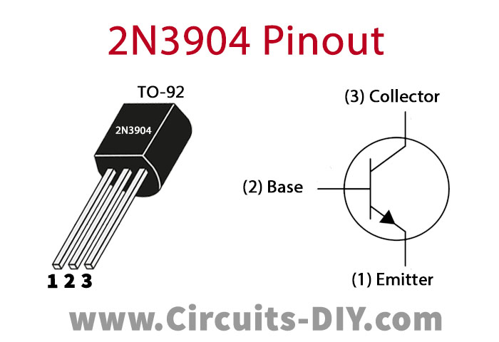
For a detailed description of pinout, dimension features, and specifications download the datasheet of 2N3904
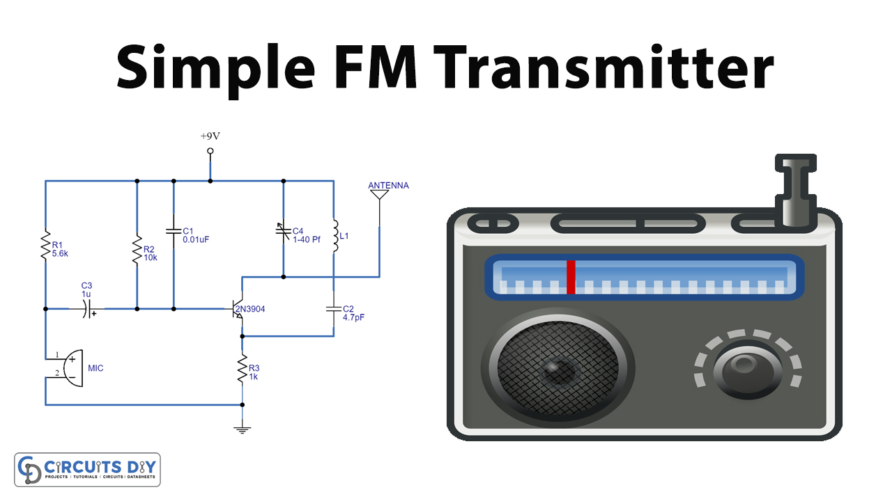
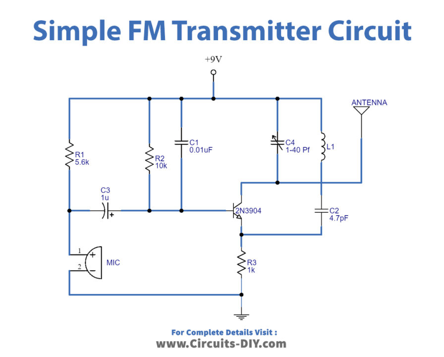
FM Transmitter Circuit
Working Explanation
The circuit diagram is shown for the FM transmitter. The microphone is assumed to catch the sound signals and there is the presence of a sensor with a capacitance value inside it. The air pressure around the mic produces such capacitance. The oscillator is required to generate carrier waves in the FM transmitter. The oscillation circuit consists of the transistor (2N3904), inductor, and variable capacitor. When current is passed through L1 Inductor and the variable capacitor, the FM Transmitter Circuit will start oscillating with the resonant frequency of the carrier signal. The transmitter circuit stores energy for oscillation as it is obtained from LC circuits. The audio signal obtained from the microphone passes through the base of the transistor to modulate the output signal of the LC circuit in the form of FM.
The main purpose of the variable capacitor is to change the resonance frequency to obtain the best FM signal band. Then, the modulated signal is transmitted or radiated as radio waves at a frequency in the FM frequency range. The antenna is just a good conductor. We use 30 cm long copper wire.
Applications and Uses:
- FM transmitter circuits are used in wireless sound systems in vehicles and offices.
- FM transmitters are used to reduce noise in certain places.