Introduction
We are living in a world where wires are decreasing day by day. And, it just did not happen instantly but it was a dream of someone. Nikola Tesla invented the Tesla coil for that purpose in the year 1891. And now after so many years, these coils are still a part of so many great inventions. And it’s not wrong to say that it’s a part of our daily gadgets, laptops, remote controls, and even smartphones that use this amazing coil. One of the greatest facts is that it doesn’t use heavy or complex circuitry and thus it’s easy to make. So let’s make a “Mini tesla coil Circuit” in this tutorial.
What is Tesla coil and How does it Work?
Do you know the oscillators? The circuits generate waves of a particular frequency. Tesla coils work the same, thus it generates a particular frequency from the range of 20KHz to 100GHz. Since this name is called the radio frequency range, therefore the tesla coil is known as the radio-frequency oscillator.
There are two coils in the circuit, the primary coil emits a great amount of current into the secondary coil and helps to drive the secondary circuit, Thus the circuit’s basic principle is to obtain the resonance.
Hardware Required
| S.no | Component | Value | Qty |
|---|---|---|---|
| 1. | NPN Transistor | 2N2222A | 1 |
| 2. | Inductor 3 turns, 275 turns | – | 1 |
| 3. | LED | – | 1 |
| 4. | Switch | – | 1 |
| 5. | Battery | 9V | 1 |
| 6. | Resistor | 22KΩ | 1 |
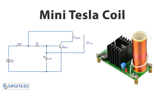
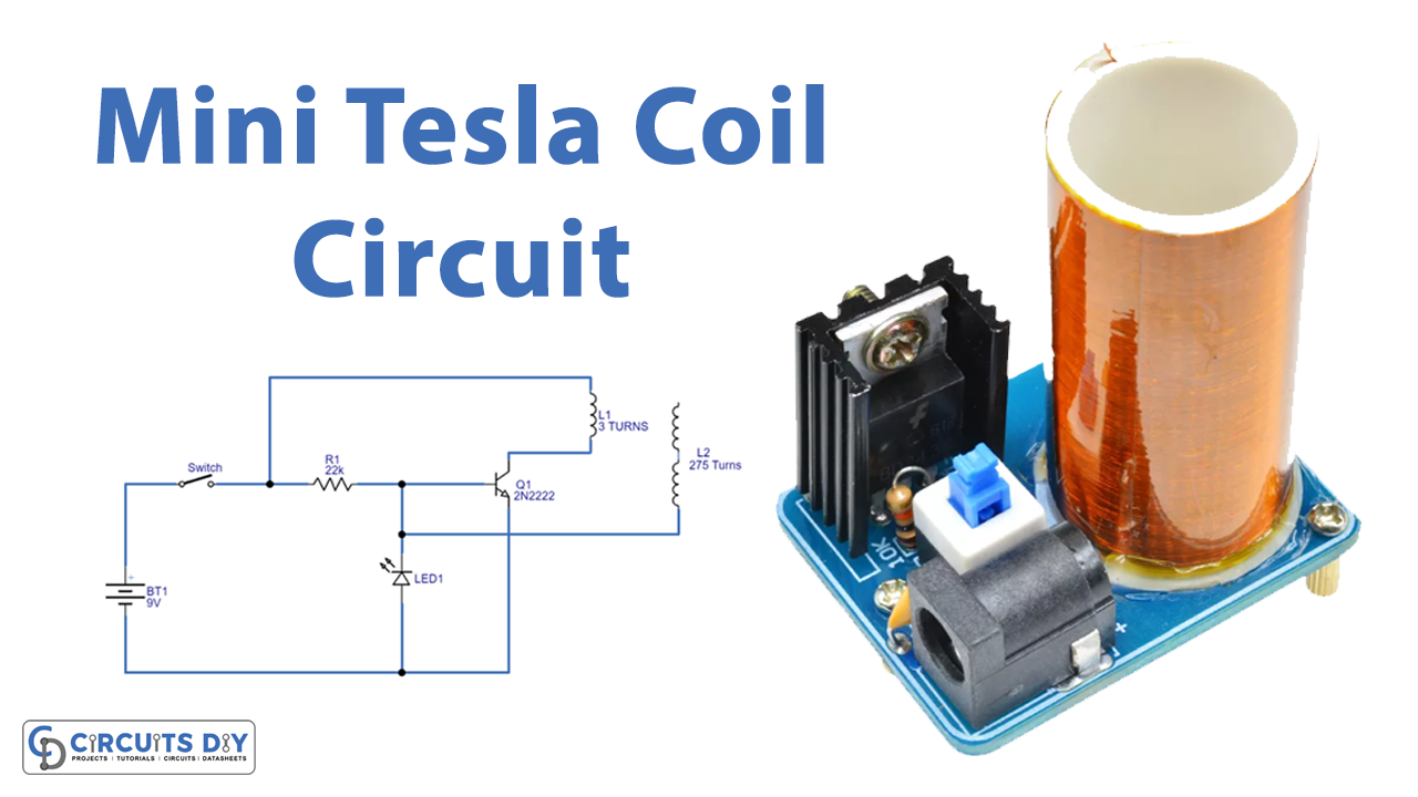
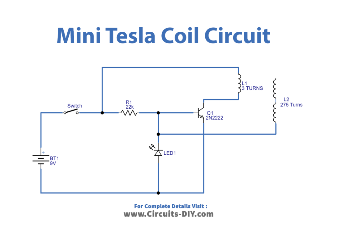
Circuit Diagram
Working Explanation
To make this circuit, you first need to make a coil setup. For this, take the PVC pipe and make three turns of conducting wire for primary coil L1. Make 275 turns of Enamelled Copper Wire for the secondary coil. First, complete the secondary winding on the pipe, then complete the primary winding of 3 or 6 turns.
In this Mini tesla coil Circuit when you provide the 9V battery supply to the circuit, initially the wired Q1 transistor remains off, thus the coil L1 gets the supply. Due to that supply in coil L1, the magnetic flux gets induced near that, and when that magnetic flux get induces in the coil L2, it will generate a higher voltage (as the coil turns of L2 are much greater than L1). Now the base of the transistor gets active. The power supply through the resistor R1 to the base of the transistor gets dropped, and the transistor goes into saturation condition. Thus the cycle continues until the supply gets turned OFF.
Application and Uses
- For spark plug ignition
- To produce artificial lights
- In vacuum system.
- Applications that need to produce high voltages at low currents can use this.
- Some new inventions of smartphones that have built-in functions of wireless charging