Sensors, mostly robotic and digitalization, are a crucial part of electronics. Electronic device sensors make our society simpler, without operator interaction, by automatically sensing and controlling the devices. The sensors, such as fire sensors, rain sensors, user inputs, heat sensors, IR sensors, etc. are various. This blog entry will explain how the IR sensor works and how the IR sensor module is built.
Hardware Component
The following components are required to make IR Sensor Module Circuit
| S.no | Component | Value | Qty |
|---|---|---|---|
| 1. | IR pair (IR LED and Photodiode) | – | 1 |
| 2. | Resistor | 10K, 100K, 330 Ohm, 10K Var | 1, 1, 1, 1 |
| 3. | IC | LM358 | 1 |
| 4. | LED | – | 1 |
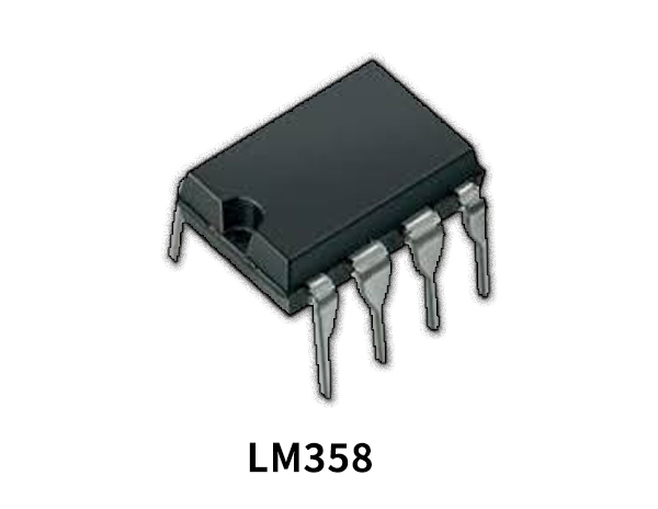
LM358 Pinout

For a detailed description of pinout, dimension features, and specifications download the datasheet of LM358
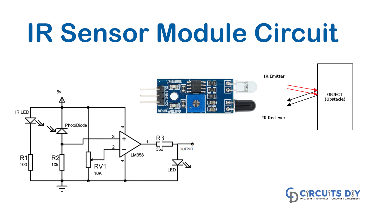
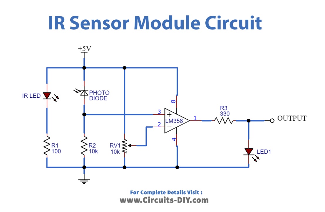
IR Sensor Module Circuit
Circuit Operation
The IR sensor circuit diagram explains the links. The photodiode is connected to the variable resistor by all LM358 (PIN 2) inverting ends to change the sensor’s sensitivity. And the photodiode and resistor linkage is joined to the non-inverting end (PIN 3).
There is no IR radiation to the photodiode when we switch ON the circuit, and the comparator output is LOW. If we take an item (not a black object) in front of an IR set, the IR emitted by an IR LED reflects the thing and ejects it. The voltage drops across the photodiode, and the voltage across the resistance R2, now increases as reflected IR Falls on Photodiode. When the voltage at R2 (connected to the comparator’s non-inverting end) is greater than the voltage at the inverted end, the result is Important.
Applications and Uses
Detector infrasound emits or senses infrared radiation to get its setting. There was a mistake. The basic idea for an infrared sensor used to send an infrared signal is to transfer this simple pleasure signal from an image, and the signal is received in an indirect receiver.