In this tutorial, we are going to show you two different projects of Simple burglar alarm circuits. There are lots of burglar alarms available in the market which you can use to build with different techniques to get alerts of any burglar.
In this circuit, the technique used is simple and effective and can be easily used at the door for home security purposes. This circuit can be built in a few seconds as it uses just a few components, even if you’re a beginner or not really familiar with circuits you can still make it easily by following this tutorial.
Hardware Components
The following components are required to make Burglar Alarm Circuit
| S.no | Component | Value | Quantity |
|---|---|---|---|
| 1. | DC Supply | 12V | 1 |
| 2. | Resistor | 100K | 2 |
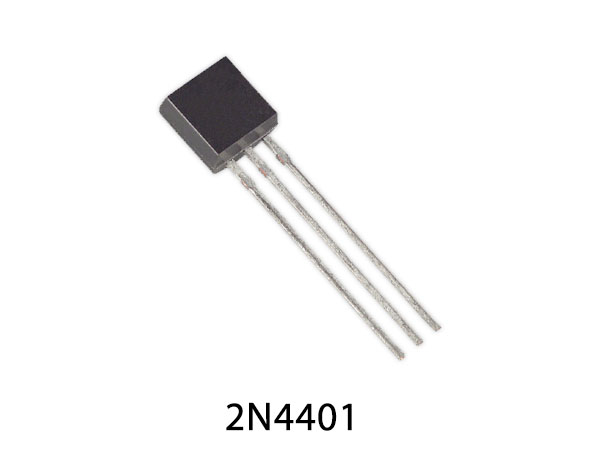
| 3. | Transistor | 2N4401 | 2 |
| 4. | Relay | 12V | 1 |
| 5. | Horn/Siren/alarm | – | 1 |
| 6. | Diode | 1N4007 | 1 |
2N4401 Pinout
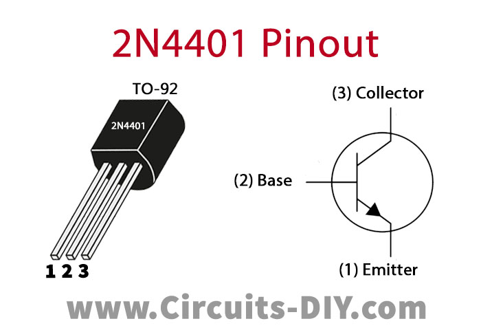
For a detailed description of pinout, dimension features, and specifications download the datasheet of 2N4401
Burglar Alarm Circuit


Working Explanation
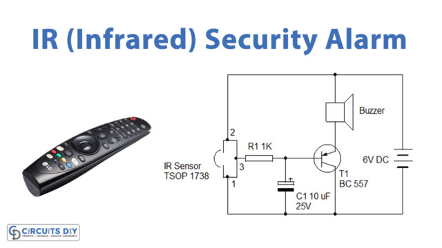
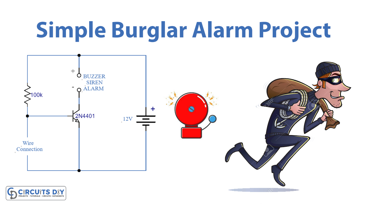
The operating voltage of this circuit is 12V. In both circuits, two points of the wire connections are connected to a very thin copper wire from one end to another at the door, ( or any place where you want security). Whenever someone will pass through that place the wire will break and the transistor will get the input signal and it switches on activating the device connected to it. The device can be either a buzzer, siren, horn, or alarm.
Circuit 1 is using just two components, a transistor, and a resistor. At the output, you can connect any device of 12V and 200-300mA current rating sire, buzzer, alarm, or horn. The second circuit is using a 12V relay at the output along with other components. You can connect any type of alarm device having a current rating of 10mA to 10A.