Introduction
We have a bunch of blogs where we have discussed the light circuits, including decorating lights, Flashlights, light strobes, emergency light circuits, etc. But, in this tutorial, we are going to make a “Simple Up/Down Fading LED Circuit”. Now, the question is what is fading light? How does it work? And where do we use that circuit? Yes! we have all the answers to your question that we are going to provide you in this article.
So, coming toward the first question, what is fading light? Fading light is that increases or decreases the intensity depending on different parameters. For example, some automatic fading lights change their intensity depending on people entering or leaving the place, some have dimmer to change the intensity. Thus, it depends on our preference.

Hardware Components
Fading LED Circuit
| S.no | Component | Value | Qty |
|---|---|---|---|
| 1. | IC | NE555 Timer | 1 |
| 2. | Transistor | BC547 | 1 |
| 3. | IR LED | – | 1 |
| 4. | Capacitor | 47μF/16V | 1 |
| 5. | LED | – | 1,1 |
| 6. | Battery | 9V | 1 |
| 7. | 2-Pin Connector | – | 1 |
NE555 IC Pinout

For a detailed description of pinout, dimension features, and specifications download the datasheet of 555 Timer
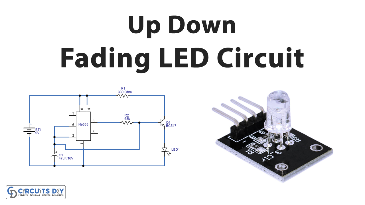
Fading LED Circuit
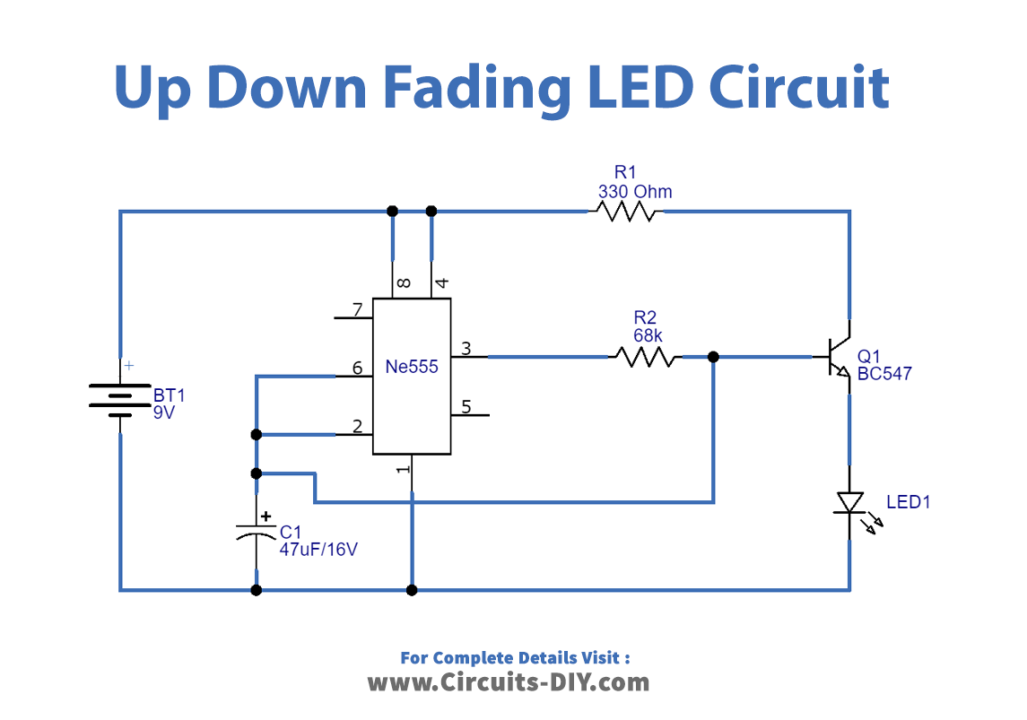
Working Explanation
This Simple Up/Down Fading LED Circuit uses the LM555 timer IC, having 8 pins. We give the power supply at pin 8, while pin 1 is for the ground. Pin 4 is the reset pin to apply the supply to reset the timer IC. Since we do not use this circuit for reset, therefore it is connected to VCC pin 8. Thus, it avoids negative triggering. Pin 6 Compares the given voltage to the terminal with the voltage of two-thirds of the VCC. The trigger pin 2 is effective for change of the flip-flop from set to reset. Hence, connected with the threshold pin 6. Output load, that is LEDs are connected at pin 3 of an IC through the NPN transistor.
Application and Uses
- In malls, restaurants, etc.
- For security purposes.
- In different decorating applications.