In this article, we are going to learn how to make an Automatic ON-OFF Buzzer Using a 555 Timer. A buzzer is a high-frequency oscillator circuit used for generating a buzzing sound through a speaker or a transducer. In an Automatic ON-OFF Buzzer, we use a speaker due to which this buzzer is louder as compared to other circuits. This circuit will produce a continuous sound of beep beep through a speaker, it is useful, easy to understand, and implement.
Since this is an automatic on-off circuit we have connected two 555 ICs as an astable multivibrator. An astable multivibrator produces rectangular waves continuously without the aid of external triggering, therefore the buzzer will be switching on and off. You can also make an astable vibrator using transistors but using 555 timers is simple, stable, easy to design, and has a low cost. Due to these reasons, the 555 timer IC has a large number of applications in electronic projects
Hardware Components
The following components are required to make the Automatic ON-OFF Buzzer Circuit
| S.no | Components | Value | Qty |
|---|---|---|---|
| 1. | IC | NE555 Timer | 2 |
| 2. | Speaker | 8 ohms | 1 |
| 3. | Resistor | 10K, 1K, 22K | 1, 1, 1 |
| 4. | Electrolytic Capacitor | 10µF, 100µF | 1, 1 |
| 5. | DC Supply | 9-12V | 1 |
| 6. | Variable Resistor | 500KR, 100KR | 1, 1 |
| 7. | Ceramic Capacitor | 18nF | 1 |
| 8. | Breadboard | – | |
| 9. | Connecting Wires | – | 1 |
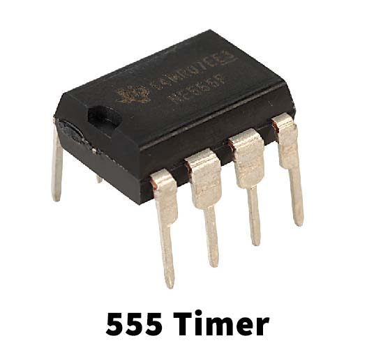
NE555 IC Pinout

For a detailed description of pinout, dimension features, and specifications download the datasheet of 555 Timer
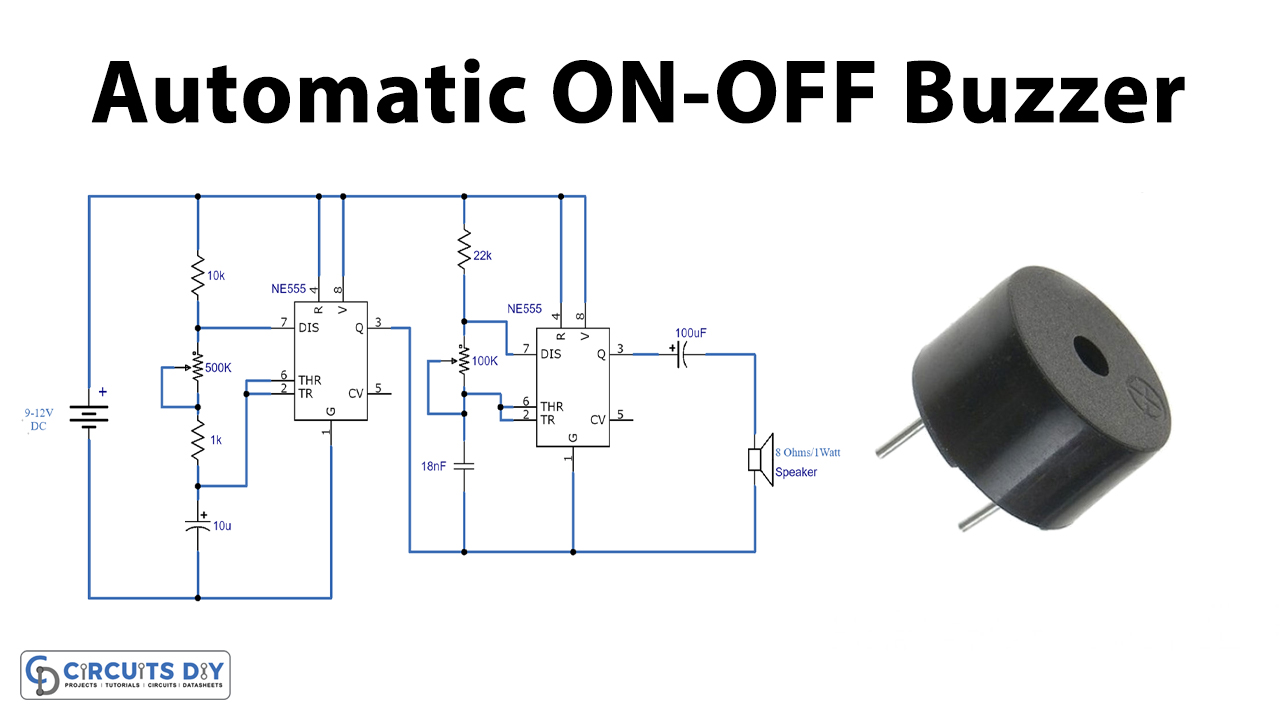
Automatic ON-OFF Buzzer Circuit

Working Explanation
Let’s take a look at the working of this circuit.
- This circuit works by using a 9-12V battery. Two 555 timer ICs are working together as Astable multivibrators.
- Power is supplied through the Vcc pins of the IC (pin 8), and capacitors are connected at the trigger and threshold pins of the IC (pins 2 and 6).
- Astable multivibrators along with capacitors are responsible for continuously providing High and low signals in the circuit.
- The on and off the speed of the buzzer can be controlled through variable resistors used in the circuit.
- The output is at the Pin 3 of the ICs which further goes through capacitors, and finally, the buzzer sound is coming through an 8ohms speaker.
Applications and Uses
This can be used for making the following circuits,
- Beeper circuits
- Alarm circuits
- Loud buzzer circuits