Introduction
To double the output to its input supply a circuit known as a voltage doubler is used. So, maybe the question arises in your mind what is the advantage of this voltage doubler circuit? So, the answer is that through this circuit you can create higher voltage from an inexpensive power transformer. Thus, In a few applications, heavy transformers can be replaced by the voltage doubler circuit. Moreover, Through this, you may also create negative voltage by reversing the polarities of the diode and capacitors. Thus the circuit can be made in various ways. Now, in this tutorial, we are going to “Simple IC 555 Voltage Doubler Schematic”
Hardware Required
| S.no | Component | Value | Qty |
|---|---|---|---|
| 1. | Timer IC | LM555 | 1 |
| 2. | Diode | 1N4007 | 2 |
| 3. | Capacitor | 33μF/50V, 0.01μF | 2, 2 |
| 4. | Resistor | 8.2KΩ, 30KΩ | 1, 1 |
| 5. | Battery | 5V-9V | 1 |
| 6. | 2-Pin Connector | – | 2 |
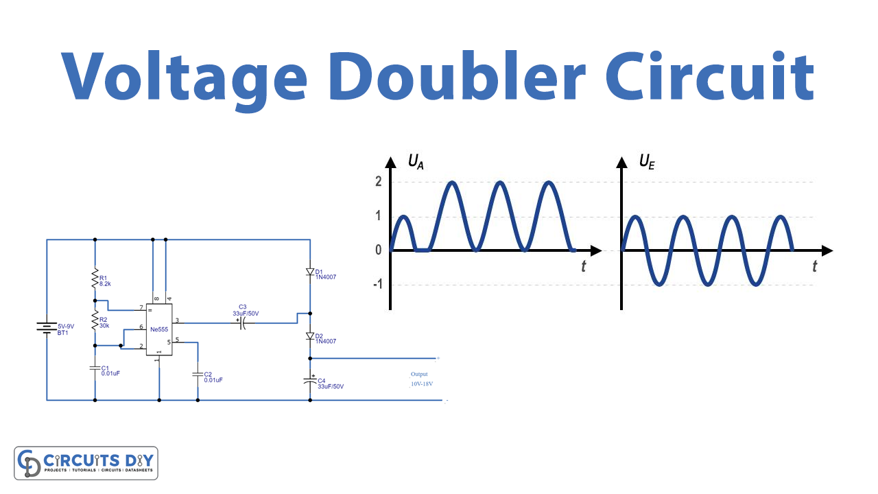
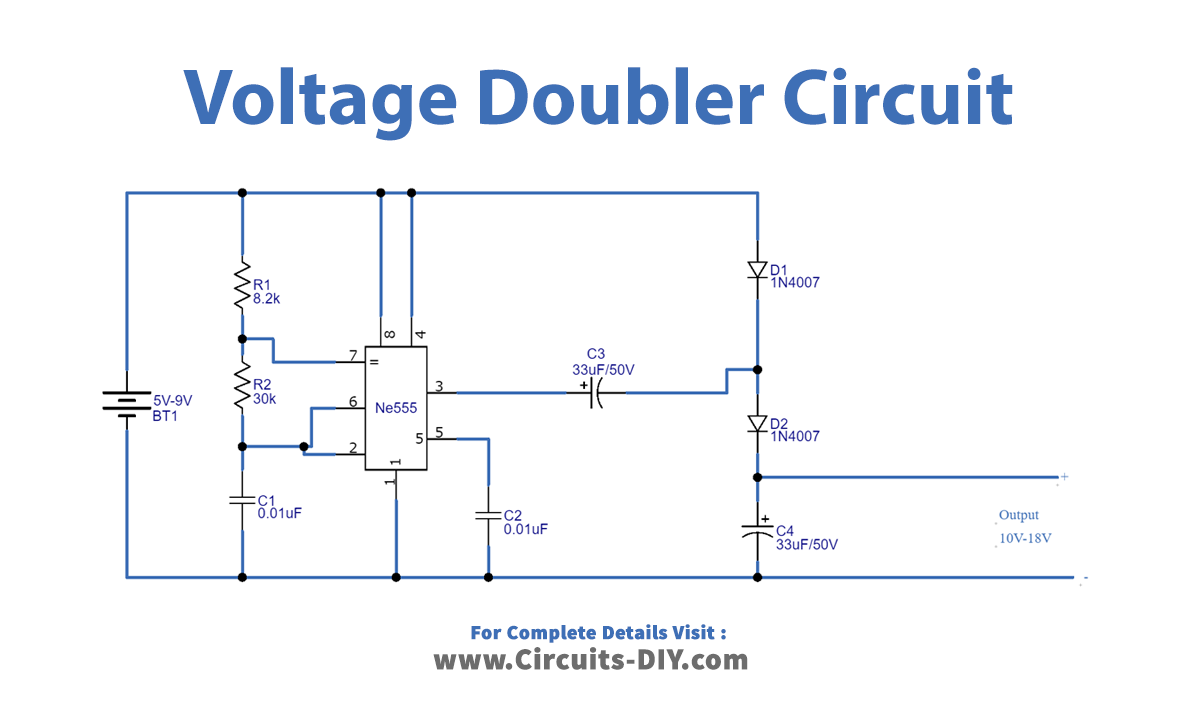
Circuit Diagram
Working Explanation
This Simple IC 555 Voltage Doubler Schematic contains the resistors R1, R2, and C1 as the timing components. Now by changing the values of these timing components you can easily get different levels of output. But don’t set these components in a way that provides very low or very high frequency. Because very low and very high frequencies coming from the timer cannot give a great output this circuit doesn’t contain any over-current draw protection setup and the load current output is slightly unstable. Therefore this circuit only works for low-current applications.
Application and Uses
- It can be used Ion pump.
- It is also used in television CRT.
- Moreover, it can be used in radar equipment.