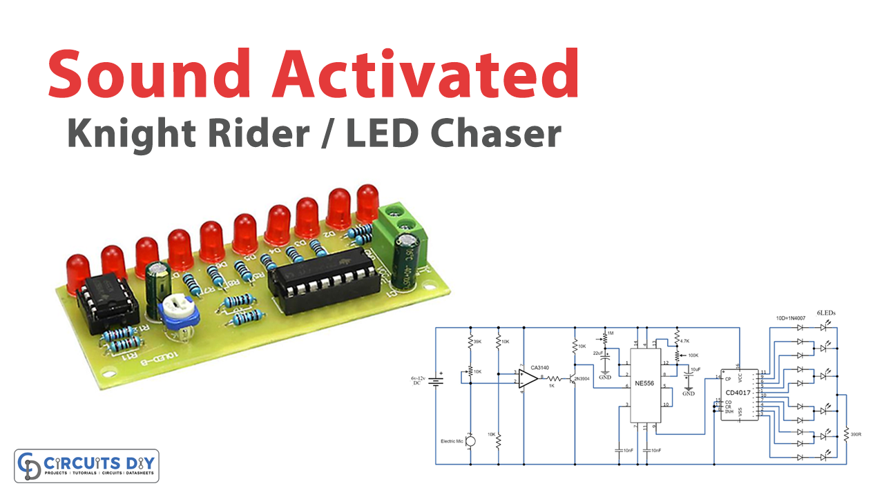
Here is an extremely intriguing DIY project of a sound-activated knight rider/LED chaser circuit. The circuit will create a running LED light effect from right to left for a brief time frame period when any sound is received by the microphone. After the brief time frame, it will go consequently OFF till any other sound is received by the microphone.
You see LED chasers light all over, in TV shows (Knight Rider), films, and store windows. This schematic is the most simple and easy design of a basic LED chaser. This project is economical and easily accessible.
Hardware Components
The following components are required to make Sound Activated Knight Rider
| S.no | Components | Value | Qty |
|---|---|---|---|
| 1. | IC | CA3140 | 1 |
| 2. | Decade counter | CD4017 | 1 |
| 3. | IC | NE555 timer | 1 |
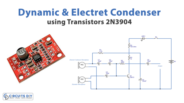
| 4. | Electret Mic | – | 1 |
| 5. | Transistor | 2N3904 | 1 |
| 6. | Variable Resistor | 10K, 1M, 100K | 1, 1, 1 |
| 7. | LEDs | – | 6 |
| 8. | Electrolytic Capacitor | 10µF, 22µF | 1 |
| 9. | Ceramic Capacitor | 10nF | 1 |
| 10. | Resistor | 39K, 10K, 4.7K, 390R | 1, 3, 1, 1 |
| 11. | Battery | 6-12V | 1 |
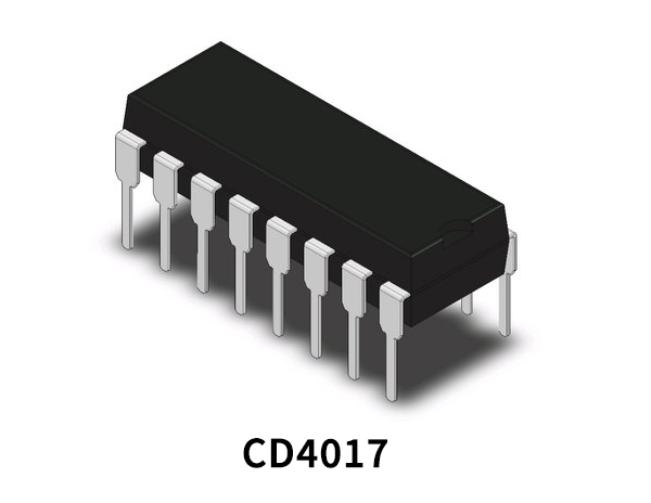
CD4017 Pinout
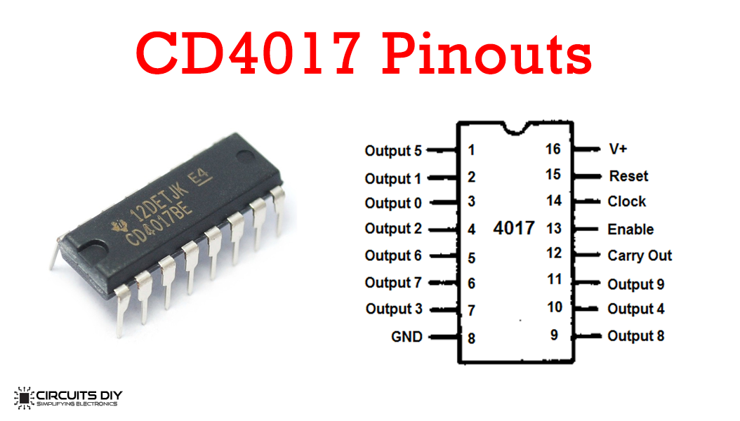
For a detailed description of pinout, dimension features, and specifications download the datasheet of CD4017
CA3140 Pinout
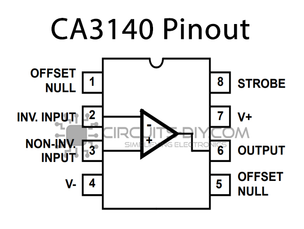
For a detailed description of pinout, dimension features, and specifications download the datasheet of CA3140
NE556 Pinout
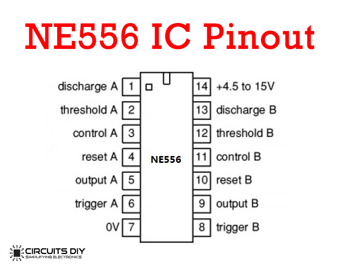
For a detailed description of pinout, dimension features, and specifications download the datasheet of 556 Timer
Sound Activated Knight Rider Circuit

Working Explanation
The circuit utilizes three ICs. The primary IC is a CA3140 operational amplifier IC that is working in comparator mode in the circuit. The subsequent IC is an NE556 timer which is a dual form of an NE555 timer IC. It contains two separate NE555 timers ICs in a single bundle. Right now, the ICs in NE556 are utilized independently. The main IC inside is utilized as a timer and the subsequent one is utilized as a flasher.
The third IC of IC is a CD4017 decade counter IC that will deliver the Knight rider or right to left running LED impacts for a preset time span that will begin after the sound is received. This time frame can be increased or decreased by expanding or diminishing the estimation of the 22µF electrolytic capacitor. The time span can be balanced with the 1M variable resistor. The running velocity of the LEDs can be balanced with the 100K variable resistor.
Applications and Uses
These circuits can be employed on:
- Automobiles like cars, buses, rickshaws, trucks, and buses for decoration purposes
- They can be used for decoration purposes like home decoration, parties, store windows, and so forth.