In this tutorial, we will show you how to make a “Clap Switch” using a 555 timer IC. This circuit can be used to control AC loads such as lights, fans, etc through Clapping. Whenever you clap near the microphone, clap Sound will trigger the 555 timer and your output will be turned ‘ON’ whether you are using Led or Relay.
In order to use this circuit (module), the clap sound should not be much far from the device. A perfect pitch will create perfect signals to turn on the desired output.

Hardware Components
The following components are required to make Clap Switch Circuit
| S. NO | Component | Value | Qty |
|---|---|---|---|
| 1. | Breadboard | – | 1 |
| 2. | Battery | 9v | 1 |
| 3. | Connecting Wires | – | 1 |
| 4. | IC | NE555 Timer | 1 |
| 5. | NPN Transistor | BC547 | 1 |
| 6. | Condenser Mic | – | 1 |
| 7. | Resistors | 220 ohms, 1k, 47k, 100k | 1, 1, 1, 1 |
| 8. | Electrolytic Capacitor | 10uF | 1 |
| 9. | LED | 5mm | 1 |
555 IC Pinout

For a detailed description of pinout, dimension features, and specifications download the datasheet of 555 Timer
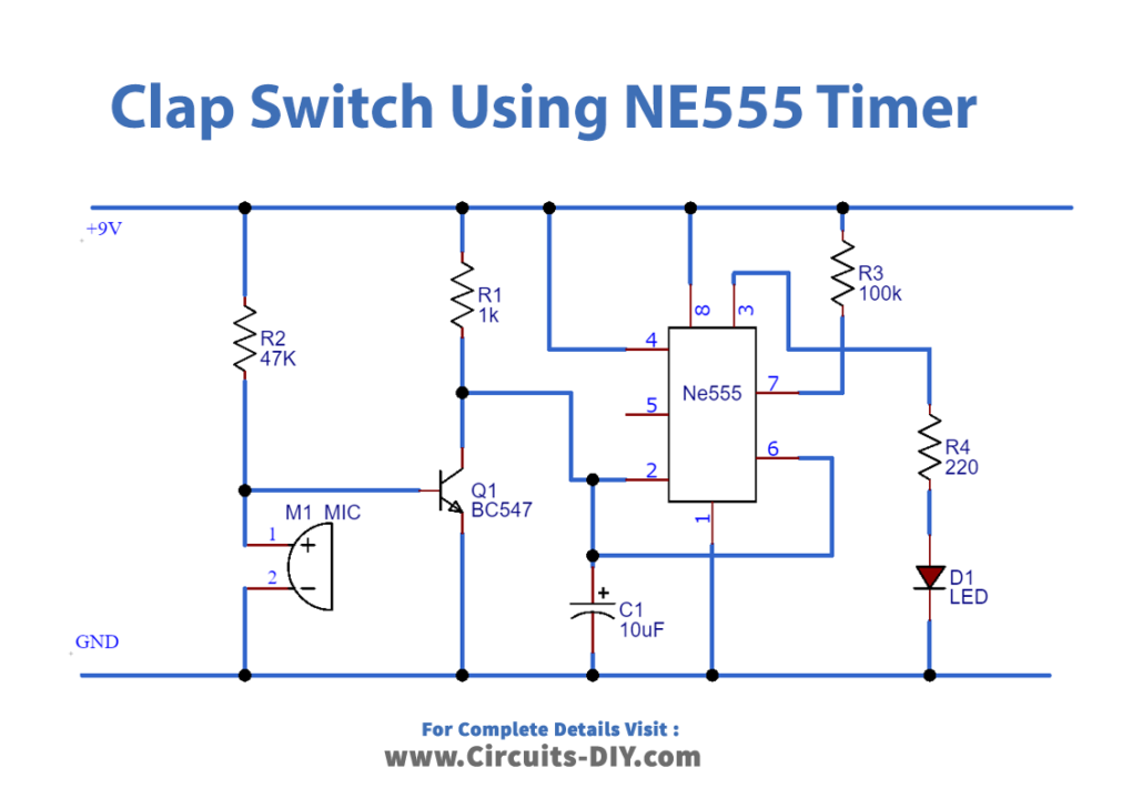
Circuit Diagram
Working Explanation
You will see in the circuit diagram in the normal state base of a transistor (BC547) will not get enough voltages (0.7v) to turn ON. The trigger pin of the transistor is connected to high potential. In order to trigger 555 through the trigger pin, there should be Vcc/3 voltages on the trigger pin.
As we know that MIC converts sound signals into electrical signals. Now the clap sound near the mic will produce a voltage across the mic. This causes to provide enough voltages to turn ON the base of the transistor. When the transistor is turned ON it will trigger NE555 because of Vcc/3 on the trigger pin. At the output, we have a 220-ohm resistor connected with an LED. When 555 timers are turned on by trigger pin output LED will be turned ON and we have an indication of output.
After some time LED indication will be turned OFF because we are using a transistor in Monostable mode. Output led ON time based on values of 1.1*R3*C1 so, we can change values of R3, and C1 to get the desired time using the formula.
Above that, we can control 220v appliances by modifying this circuit output. If we use a relay module at output instead of Led we can control 220v appliances through clapping.
Application
- Control Home Appliances by clapping like Lamps etc