Introduction
Making circuits are fun but sometimes the experience gets horrible when we try our best but the circuits don’t work. In that case, we try everything, from continuity to the right wiring, but sometimes we forget to test or check the IC. Hence, we give up. So, when you get stuck and your circuit doesn’t work testing an IC is a great option. However, not every IC can be tested in the same way. In this article, we are talking about the testing of two very common ICs. So, in this tutorial, we are going to “IC 555/IC 741 tester”.
Hardware Required
| S.no | Component | Value | Qty |
|---|---|---|---|
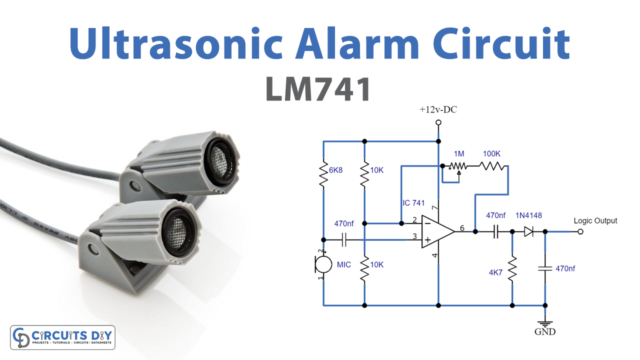
| 1. | Op-amp IC | UA741 | 1 |
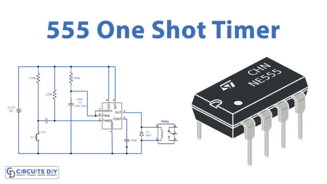
| 2. | IC | NE555 Timer | 1 |
| 3. | LED | – | 3 |
| 4. | Switch | – | 1 |
| 5. | Capacitor | 10uF/16V, 0.01uF | 12 |
| 6. | Resistor | 68KΩ, 33kΩ, 12kΩ, 4.7kΩ | 1, 1, 3, 2 |
| 7. | Battery | 9v | 1 |
Circuit Diagram
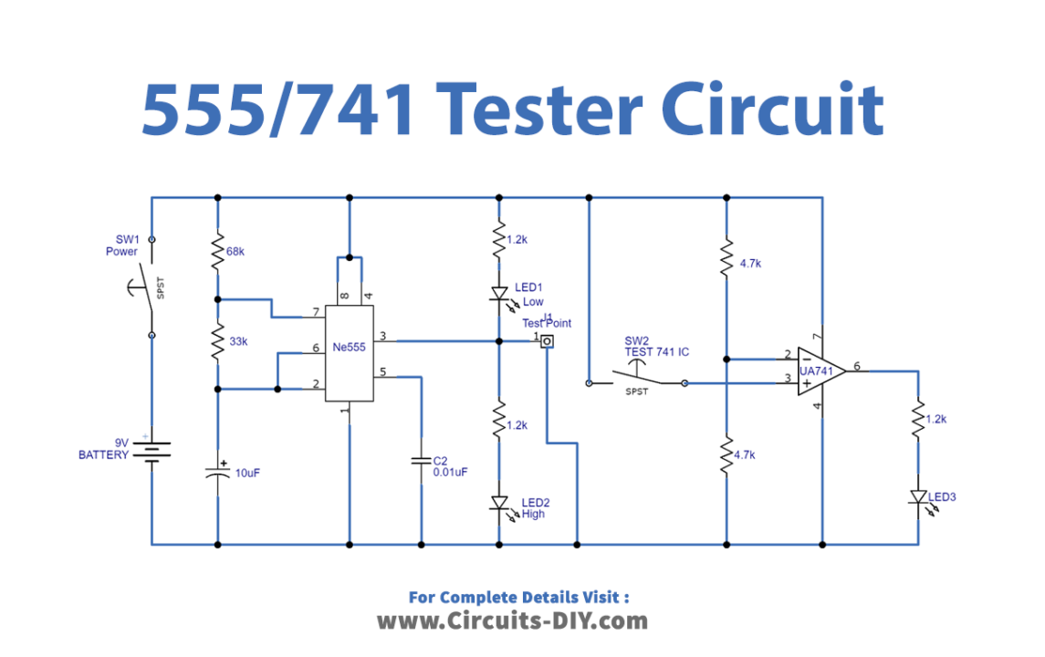
Working Explanation
Through this IC 555/IC 741 tester circuit, you can easily test the two most familiar Integrated circuits which are the 741 operational amplifier IC and 555 timer IC. Both the ICS has 8 pins. After the circuit gets wired, to check IC555 observe the output LEDs connected at pin 3. These ICs should glow alternately. If these two connected output LEDs glow alternately, it means the IC is perfect. In another case, there can be a fault in an IC. Similarly, to test opamp IC741 and observe the output LED associated with IC741, the LED should turn ON, otherwise, there must be a defect in an IC.
Application and Uses
- To test the 55 5 timer IC.
- To check the 741 opamp IC.