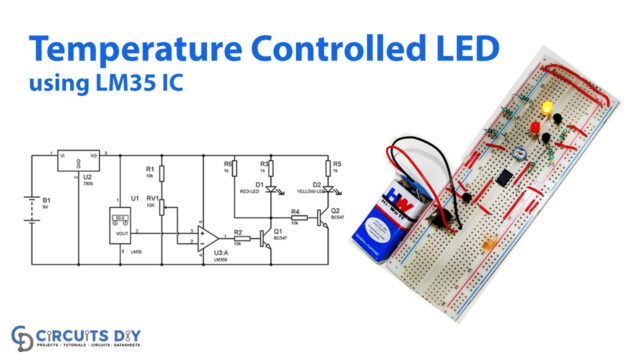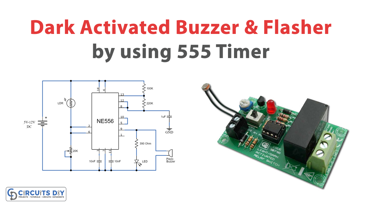
Here is a fascinating DIY project tutorial of a dark-activated buzzer & flasher utilizing 556 IC. The circuit will squint an LED and blare the signal when there is no light on the surface of the LDR. The circuit uses 556 IC, which is a double-timer IC. It contains two 555 clock ICs in a single bundle. More details regarding 556 IC are mentioned below.
For this circuit, you can utilize a 5-volt to 12-volt battery as the DC power source, or if you have a DC power adapter, you can alter the output so that it gives out a normal of 5 to 12 volts. For this circuit, you will require a few jumper wires to associate all the resistors and capacitors to the 556-timer chip that gets confounded.

Hardware Components
The following components are required to make a Dark Activated Circuit
| S.no | Component | Value | Qty |
|---|---|---|---|
| 1. | IC | NE555 Timer | 1 |
| 2. | Piezo Buzzer | – | 1 |
| 3. | LDR | – | 1 |
| 4. | Potentiometer | 20k | 1 |
| 5. | LED | – | 1 |
| 6. | Resistor | 100k, 390 ohms, 220k | 1, 1, 1 |
| 7. | Ceramic Capacitor | 10nF | 2 |
| 8. | Electrolytic Capacitor | 1uF | |
| 9. | Battery | 5 volts – 12 volts | 1 |
NE555 IC Pinout

For a detailed description of pinout, dimension features, and specifications download the datasheet of 555 Timer
Dark Activated Circuit
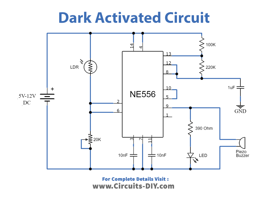
Working Explanation
Meanwhile, the operation of the circuit is simple and straightforward. However, the affectability of the dark sensor can be balanced with the 20K variable resistor. You can likewise expand the number of LEDs by primarily associating in corresponding with the 390 ohms resistor, or you can interface a few LEDs in every arrangement series with a reasonable current restricting resistor. On the off chance that you are utilizing 3 LEDs in a single arrangement, at that point it will be essential to work the circuit with a voltage at least 9V.
Applications and Uses
It is an advanced version of the dark-activated LED circuit, which is likewise utilized in the following electronic devices:
- Dark sensing alarms
- Light sensitive rooms
- Emergency indicators