Introduction
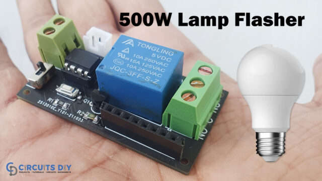
When there are such countless circuits that are likewise hard to make, there are additionally a few circuits that are amusing to make. We generally attempt to make various kinds of circuits, in some cases we attempt to carry out little complicated circuits to make them easier for you guys. While some of the time we attempt energetic and fun circuits that can break your boredom. Thus, this article is a mixture of both complication and fun. Because here we are going to control the lamp flasher circuit using the controller. So, in this tutorial, we will make 500W LED Lamp Flasher using Attiny85 – Arduino Compatible.
The circuit involves an 8 Pin Attiny85 Microcontroller as Arduino, its exceptionally compatible board comprises Relay, TSOP1838 Infra-Red Receiver, and a 3 Pin male header with analog input to interface sensors. Thus, the project is a great example to shrink Arduino circuits into more compact forms.

JLCPCB is the foremost PCB prototype & manufacturing company in china, providing us with the best service we have ever experienced regarding (Quality, Price Service & Time).
Hardware Components
The following components are required to make LED Lamp Flasher Circuit
| S.no | Component | Value | Qty |
|---|---|---|---|
| 1. | Arduino | UNO | 1 |
| 2. | USB Cable Type A to B | – | 1 |
| 3. | Jumper Wires | – | 1 |
| 4. | Breadboard | – | 1 |
| 5. | Attiny85 | – | 1 |
| 6. | Relay | 5V | 1 |
ATtiny85 Pinout

For a detailed description of pinout, dimension features, and specifications download the datasheet of ATtiny85
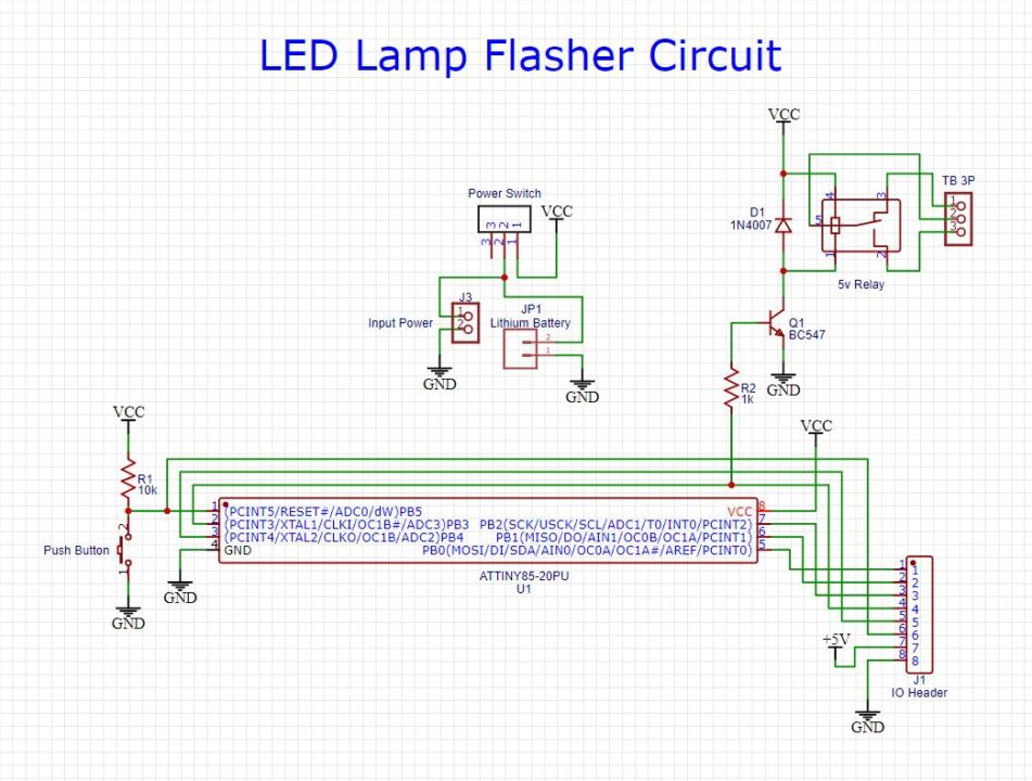
LED Lamp Flasher Circuit
Code
// Circuits DIY
// For Complete Details Visit -> https://circuits-diy.com

void setup() {  // initialize digital pin 13 as an output.
   pinMode(3, OUTPUT);
}

void loop() {
   digitalWrite(3, HIGH);
   delay(1000);
   digitalWrite(3, LOW);
   delay(1000);
}
Working Explanation
This is our circuit of up to 500W Lamp Flasher utilizing AT-TINY85 board. Here the circuit drives 230V AC 100W light. But, it can also drive light up to 500W. The blinking Blinking recurrence, that is frequency is 1Hz. However, the frequency of the blinking lamp can be adjusted by adjusting the delay values in the code, When you connect the circuit and upload the code, and give the supply to the circuit, the lamp starts flashing accordingly.
Code Explanation
The code is easier to understand and doesn’t require a lot of effort.
- In the void setup, we have defined the output pin. Here in our case, it is pin 3.
- In the void loop, we first give the high condition to that output pin, so that the lamp turns ON, then we give a minor delay by using the delay command, and after that, we give the low condition, so that lamp turns OFF. Thus, this makes the lamp flash.
Applications
- Vehicle indicators.
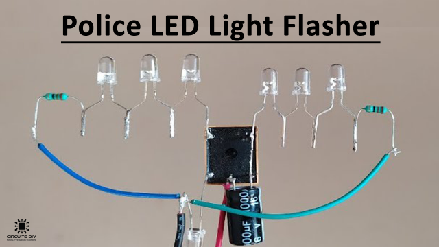
- Police sirens.
- Lightning detectors
- As a signal flashlight.
- For decoration purposes.
- for toys of children.
- In battery indicators
- In some display circuits, etc.