LEDs are probably the only components to offer a wide range of applications. It can be used either to describe the working of the circuit or with LED itself, a complete circuit can be developed. The LED flasher circuit makes use of this amazing component to turn its flash on and off. An LED flasher is a turn-signal or hazard flasher relay that works properly with LED turn-signal bulbs. Here we design a simple LED flasher circuit by using LM 3909 IC. It can operate for over one year from one C-size flashlight cell, giving a bright and high current LED pulse.
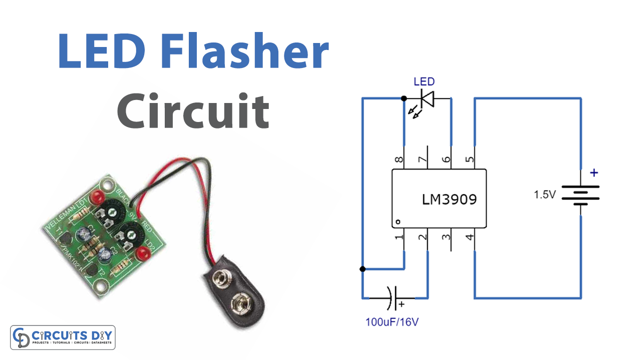
This IC requires minimum external components for its operation. It can operate from a low voltage of 1V to 5V and has a low current drain, averaging under 0.5 mA during battery life making this IC operation long-lasting. It can directly drive an 8Ω speaker. And also this IC can operate in wide temperature ranges.
Hardware Required
Circuit Diagram

Working Explanation
As we can see, the main part of the circuit is using single IC LM3909. This IC is a monolithic oscillator specifically designed to flash Light emitting diodes. This IC comes in 8 pin DIP Package. Here a timing capacitor in the circuit is used for voltage boost, it delivers pulses of 2 or more volts to the LED while operating on a supply of 1.5V or less. The circuit is inherently self-starting and requires the addition of only a battery and capacitor to function as an LED flasher.
Applications
It can be used in toys for flashing lights or siren effects. It is also useful for warning devices.