The dark-activated alarm is a circuit that is used to identify darkness or loss of light. It only produces an alarm sound in darkness because in the presence of light the alarm buzzer does not make any sound. A widely used light sensor is the LDR or Light Dependent Resistors. For this experiment, we use LDR to sense darkness, i.e when light intensity drops. The circuit requires a few general elements, such as a BC547 resistor, a UM66 Melody IC, a 2N3904 resistor, and a few others.
Hardware Components
| S.no | Component | Value | Qty |
|---|---|---|---|
| 1. | Breadboard | – | 1 |
| 2. | Connecting Wires | – | 1 |
| 3. | Battery 1.5 AA cell x2 | 3v | 1 |
| 4. | NPN Transistor | 2N3904 | 1 |
| 5. | NPN Transistor | BC547 | 1 |
| 6. | IC | NE555, UM66 | 1 |
| 7. | POT | 500K | 1 |
| 8. | Resistor | 1K, 220 ohm | 1, 1 |
| 9. | LDR | – | 1 |
| 10. | Speaker | 8 ohm | 1 |
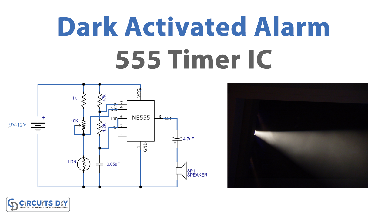
Circuit Diagram
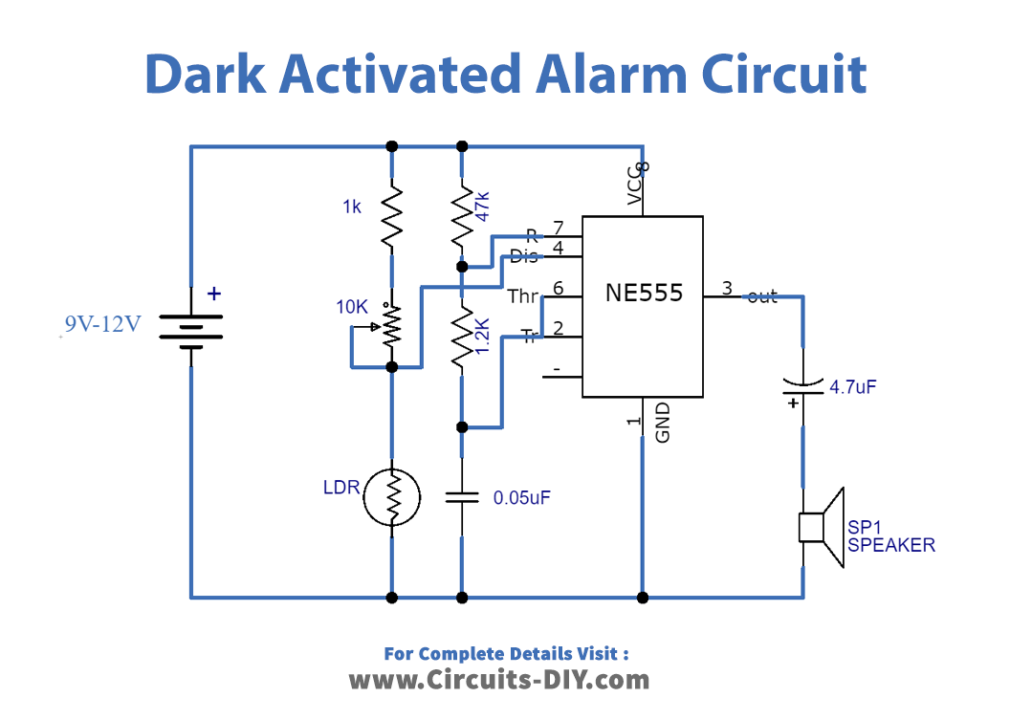
Working Explanation
The BC 547 transistor acts as a switch here. When the light-dependent resistor (LDR) detects no light on its layer, its resistance decreases, the BC547 transistor is turned on and the current begins to flow through it and stimulates the UM66 IC. The 2N3904 NPN transistor is used to enhance the melody IC output to operate an 8-ohms speaker. To change the circuit sensitivity a 500K variable resistor is used. The circuit can be worked with any size of two 1.5-volt batteries.
Applications and Uses
- Darkness detector circuits like these can be found in systems where when it is dark we can automatically turn on the lights.
- This circuit can be a part of a larger circuit or such as a home automation or home security system.