Introduction
Fire safety is a crucial aspect of any household. A smoke detector is an essential device that can alert you of a potential fire before it becomes a major catastrophe. Building your own smoke detector circuit is a fun and simple DIY project that can be completed with minimal materials and tools. With just a few essential components, such as a battery, a buzzer, and a smoke sensor, you can create a functional smoke detector that will keep you and your loved ones safe.
As you embark on this project, you’ll learn about the different types of smoke sensors, how they work, and the basics of circuit building and soldering. So, gear up for a hands-on learning experience that is both fun and informative, and create a device that will give you peace of mind.
Categories of Smoke Detector
Let’s begin with a brief primer on the smoke alarm system. There are two primary categories of smoke detectors, ionization smoke detectors, and photoelectric/optical smoke detectors.
- There is a light source and a light detector similar to a photocell in photoelectric detectors. When light enters the system, the photocell begins to function. The signal is partly generated because smoke obscures the photocell’s light source.
- In contrast, ionization detectors consist of two electrodes and a body filled with ions. These ions can move freely, and the electrodes are in their natural state when there is no smoke. Smoke impedes the free movement of these ions, rendering the electrodes ineffective.
Hardware Required
You will require the following hardware for Simple Smoke Detector Circuit.
| S.no | Component | Value | Qty |
|---|---|---|---|
| 1. | IC | LM741 | 1 |
| 2. | MQ-2 | – | 1 |
| 3. | Capacitor | – | 1 |
| 4. | Resistor | – | 3 |
| 5. | Variable Resistor | – | 1 |
| 6. | LED | – | 2 |
| 7. | Jumper Wire | – | 1 |
MQ-2 Smoke Sensor
The MQ-2 Smoke/Gas Sensor has been employed in constructing the circuit. This device is sensitive to flammable gases such as methane, propane, butane, hydrogen, LPG, and others. There are two electrodes in the sensor as well. They have a heating system composed of tin oxide and are constructed out of aluminum oxide.
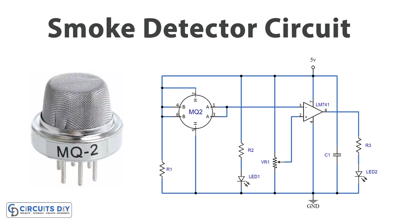
Circuit Diagram
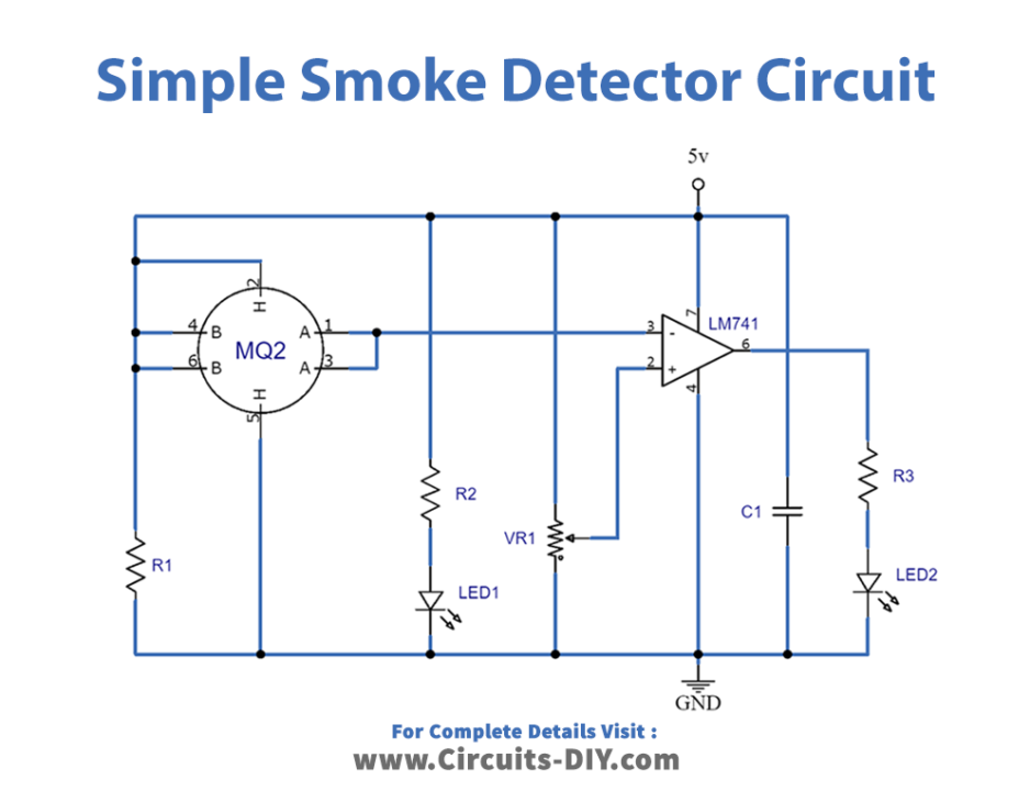
Working Explanation
We used the LM358 comparator and the MQ-2 smoke sensor to build the simple smoke detector circuit. Here, the inverted end of the LM358 is connected to Potentiometer so we can adjust the circuit’s sensitivity. LEDs are used to show what the output of LM358 is. You can use a buzzer instead of an alarm if you want to. Also, the output of the smoke sensor is connected to the part of LM358 that is not inverted.
When the air is clean, the resistance order on 50KW keeps the conductivity between the electrodes at a low level. In this case, the value of the input to the inverting terminal stays higher than the value of the input to the other terminal. This keeps the LED off.
When there is a lot of smoke from a fire, the smoke fills the sensor, and the sensor’s resistance drops to 5KW. This makes the electrodes more conductive. This process lets the comparator’s non-inverted terminal receive a high input, which leads to a high output. In this case, the LED lights up, and the fire alarm starts to sound.
Final Words
Building a simple smoke detector circuit is a fun and educational DIY project that can help you learn about circuit building and fire safety. You can create a functional smoke detector that keeps you and your loved ones safe with just a few essential components and some basic skills.
We hope this guide has been helpful and that you have the knowledge and confidence to build your smoke detector and keep your home or workshop safe from fire. Ask away any questions in the comment section, and we would love to answer your query.