In this tutorial, we will learn how to make a clap switch circuit, using a 555 Timer IC. A clap switch circuit can turn ON/OFF any electrical component by the sound of a clap. Although, the name of the circuit is a clap switch it can be turned On by any sound which has a pitch similar to a clap sound.

Hardware Components
The following components are required to make Clap Switch Circuit
| S. NO | Components | Value | Qty |
|---|---|---|---|
| 1. | Breadboard | – | 1 |
| 2. | Battery | 9v | 1 |
| 3. | Connecting Wires | – | 1 |
| 4. | IC | NE555 Timer | 1 |
| 5. | NPN Transistor | BC547 | 1 |
| 6. | Capacitor | 10uF | 1 |
| 7. | Resistors | 100k, 47k, 1k, 220 ohms | 1, 1, 1, 1 |
| 8. | LED | 5mm | 1 |
| 9. | Condenser Mic | – | 1 |
555 IC Pinout

For a detailed description of pinout, dimension features, and specifications download the datasheet of 555 Timer
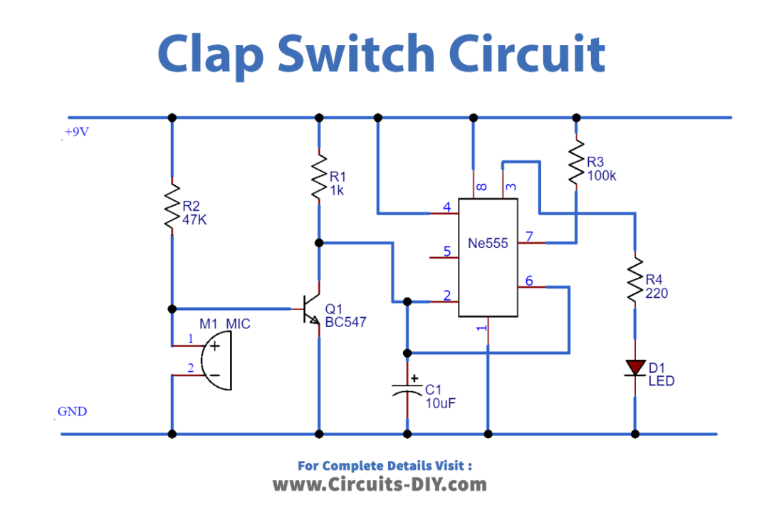
Connection
- Connect Pin 4 & 8 of 555 timers to VCC.
- Connect Pin1 of 555 timers To GND.
- Use a jumper wire to connect Pin 6 & Pin 2 of the 555 timers.
- Connect Indicating LED at Pin 3 with 220 Ω resistor.
- Connect 100K Ω resistor between Pin 7 of 555 timers & VCC.
- Use a 10uF Electrolytic Capacitor to connect Pin 2 of the 555 timers to GND.
- Place the Transistor on the breadboard & Connect the Emitter pin to GND.
- Use a 1k Ω resistor to connect the Collector pin of the transistor to VCC.
- Connect the Condensor mic between the Base of the transistor & GND.
- Use the 47k Ω resistor to connect the Base of the transistor & VCC.
Working Explanation
The main component of the clap switch is the condenser mic which works as a sound sensor in this circuit. It converts sound energy into electrical energy which then raises the potential at the base pin and turns On the transistor. The electrical signal is amplified by the transistor and then applied to the 555 timers which will trigger this IC. LED is connected to the output pin 3 of the IC through a 220 Ω resistor. The 555 timers are operating in monostable mode, so the LED will be turned OFF automatically after some time. We can change the time duration of LED by changing the values of resistor R1 and capacitor C1.
To test the circuit you have to clap loudly as this condenser mic doesn’t have long-range. If we want to control high voltage (220/110V) devices with this circuit then we can add a relay to this circuit.
Application
- This circuit will help us to switch On the lights in the dark when we can’t locate the switchboard.
- When using this circuit, there is no fear of electric shock as you don’t have to touch any mechanical switches physically