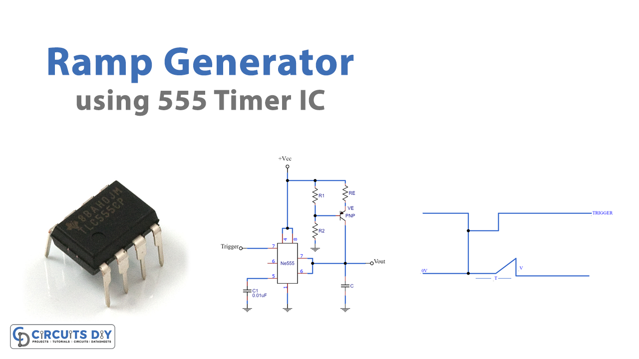
Introduction
A ramp generator is a signal generator that produces a ramp waveform at output. The waveform increases uniformly as the capacitor gets charged and reaches the peak and the waveform decreases promptly as it gets discharged. This waveform gets repeated which can be easily seen in the oscillator.
Linear ramp generators are also called sweep generators. There are various numbers of ways of ramp generation, and various methods are used for this which include, an exponential charging method, constant current charging method, Miller integration method, etc. Initially, ramp generators were carried out in the analog hardware circuit.
Hardware Required
| S.No | Components | Value | Qty |
|---|---|---|---|
| 1. | Breadboard | – | 1 |
| 2. | Timer IC | NE555 | 1 |
| 3. | Resistors | – | 2 |
| 4. | Capacitors | 0.01uf | 1 |
| 5. | PNP Transistor | – | 1 |
| 6. | Supply voltage | – | 1 |
Circuit Diagram
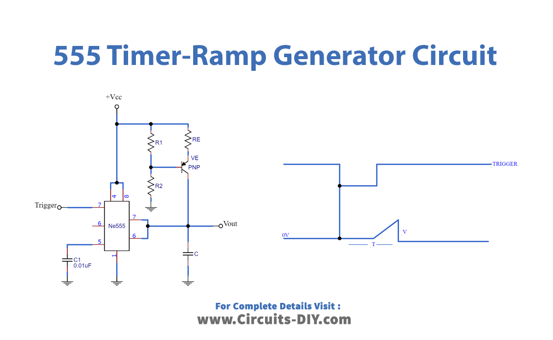
Working Explanation
IC NE555 works as an astable multivibrator in this circuit. When the capacitor gets charged from the supply voltage source, a waveform generates. The source current of the PNP transistor constantly charges the capacitor and the capacitor generates a ramp. And that’s how the circuit works. Output can be seen on the oscilloscope. The circuit works great at high frequencies same as they work at low frequencies.
Application and Uses
- It can be used to convert a digital signal to an analog signal
- It is used in 2 phase encoder
- A ramp generator with internal time measurement is one of its application
- A ramp generator with external pulses is also its application
- The constant current Ramp generator
- Bootstrap Ramp generator
- Miller integrator ramp generator
- UJT relaxation oscillator