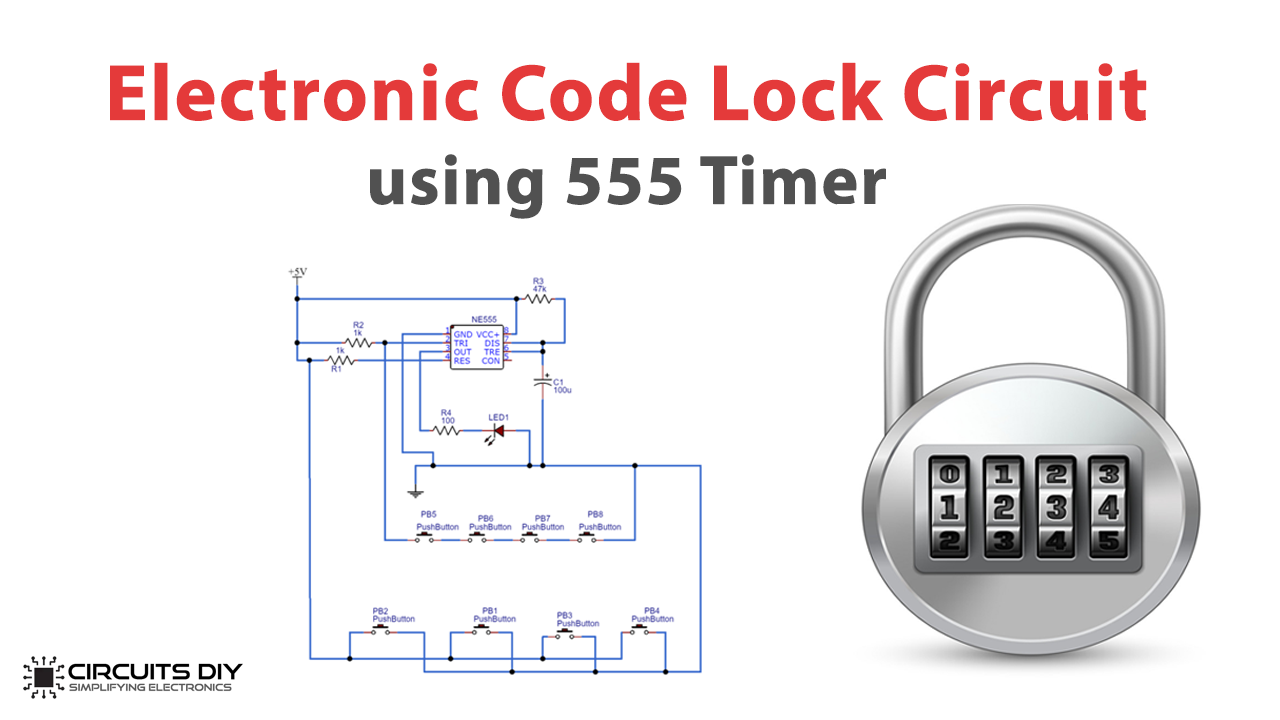
In Electronics, Digital Code Locks are very popular. These electronic code locks have uses for security purposes where you need to enter a particular ‘Code’ to open the Lock. These locks are mostly built using microcontrollers but can also be made using a 555 IC.
Here, the LED represents the Electric Lock, which remains locked when there is no current and gets unlocked when the current passes through. The combination of definite four buttons is the “Code”, which is needed to open the Lock.

Hardware Components
The following components are required to make Code Lock Circuit
| S.No | Component | Value | Qty |
|---|---|---|---|
| 1. | Breadboard | – | 1 |
| 2. | Battery | 9v | 1 |
| 3. | Connecting Wires | – | 1 |
| 4. | IC | NE555 Timer | 1 |
| 5. | Electrolytic Capacitor | 100uF | 1 |
| 6. | Resistors | 100,1k,47k | 1,2,1 |
| 7. | Push Button | – | 8 |
| 8. | LED | 5mm | 1 |
555 IC Pinout

For a detailed description of pinout, dimension features, and specifications download the datasheet of 555 Timer
Code Lock Circuit
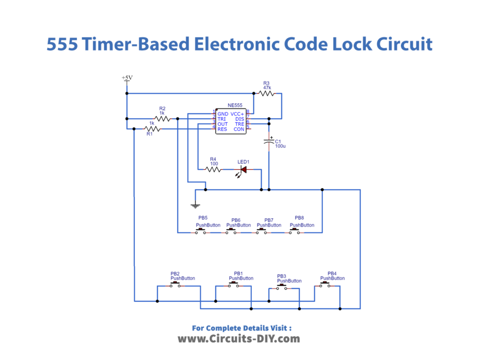
Working Principle
In this circuit, we will have an LED at the output pin 3 which turns ON when the trigger is applied by pressing those specific four buttons (code). LED remains on for some time and then turns off automatically. In this way, the LED indicates that the code is correct and unlocks the door.
Working Explanation
In this Electronic Code Lock, 555 IC is configured in Monostable Multi-vibrator mode. On pressing the push button, it gets triggered, LED will turn ON and the output will stay HIGH until the capacitor connected at PIN6 charges to the peak value. The time for which the OUTPUT remains high can be calculated by the given formula.
T = 1.1*R*C
Uses
- Provides security
- Used commonly available components
- The project is simple and easy
Applications
- This simple timer-based electronic code lock circuit has usage in residential places to ensure better safety.
- It has been used by organizations to ensure authorized access to highly secured places.
- With a slight modification, this will control the switching of loads through a password.