6V to 12V Converters are a common preference of electronic enthusiasts for low-end electronic projects. These small DC-DC converters provide a simple, easy & cheap way of building your own DC test supply for projects. So, in this project, we are going to build a simple 6V to 12V Converter circuit using a Zener diode & a NE555 precision timer IC.
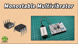
A 555 Timer IC serves as the core of this 6V to 12V converter circuit. The IC possesses an oscillation frequency ranging from 670 to 680 Hz. Here, this NE555 timer acts as an astable multivibrator An astable multivibrator is a free-running oscillator that switches continuously between its two unstable states. With no external signal applied, the transistors alternately switch from cutoff to saturation state at a frequency that RC time constants of the coupling circuit determine. If these time constants are equal (R and C are equal) then a square wave will generate with a frequency of 1/1.4 RxC. Hence, an astable multivibrator is also a pulse generator or a square wave generator.

Hardware Components
The following components are required to make 6V To 12V Converter Circuit
| S.no | Component | Value | Qty |
|---|---|---|---|
| 1. | IC | NE555 Timer | 1 |
| 2. | NPN Transistor | BD139 | 1 |
| 3. | DC Supply Input | 6V | 1 |
| 4. | Inductor | 100uH 2A/3A | 1 |
| 5. | Zener Diode | 12V/1W | 1 |
| 6. | Schottky Diode | 1N5819 | 1 |
| 7. | Ceramic Capacitors | 10nF, 560pF | 1 |
| 8. | Resistor | 1K, 10K | 1 |
| 9. | Electrolytic Capacitor | 1uF/50V | 1 |
| 10. | Breadboard | – | 1 |
| 11. | Connecting Wires | – | – |
NE555 IC Pinout

For a detailed description of pinout, dimension features, and specifications download the datasheet of 555 Timer
BD139 Pinout
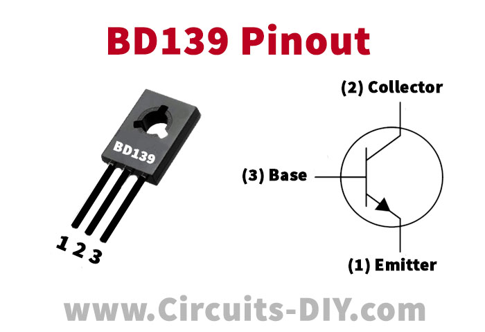
For a detailed description of pinout, dimension features, and specifications download the datasheet of BD139
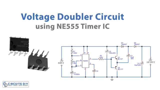
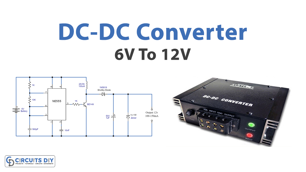
6V To 12V Converter Circuit
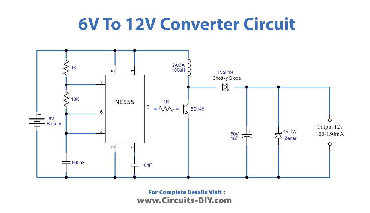
Working Explanation
The working of this circuit is quite simple. Certain frequency pulses are generated with the 555 timer IC by using 1K, 10K, and 560pF capacitors. Pin 6 and 2 of the IC are connected with each other, making the IC self trigger continuously, providing pulses at the output pin 3.
A BD139 transistor is connected to the output of the IC. When each pulse is received the transistor becomes ON and builds a decent amount of energy in the 100uH inductor and when the transistor is OFF the saved energy of the inductor is fed to the 1uF capacitor through the 1N5819 Schottky diode. The output current of the circuit is 100mA to 150mA.
Applications
- Used for industrial processes such as load matching in power industries.
- It can be used in projects where a step-up conversion of 6V to 12V is required.
- Serves in low voltage appliances such as DVD/CD Players, Speakers, etc.