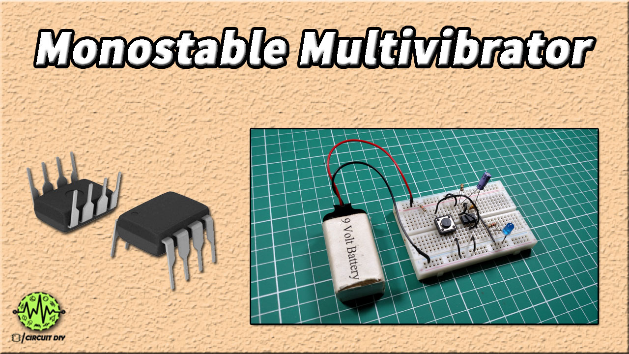
We can categorize multivibrators into three types depending on the number of stable states such as astable, monostable, and bistable. In this tutorial, we will show you how to make a Monostable Multivibrator circuit using a 555 timer IC. A monostable multivibrator is also called a one-shot multivibrator. In this multivibrator, only one state of output is stable while the other is unstable and the duration of the unstable state depends on the R-C time constant.

Hardware Components
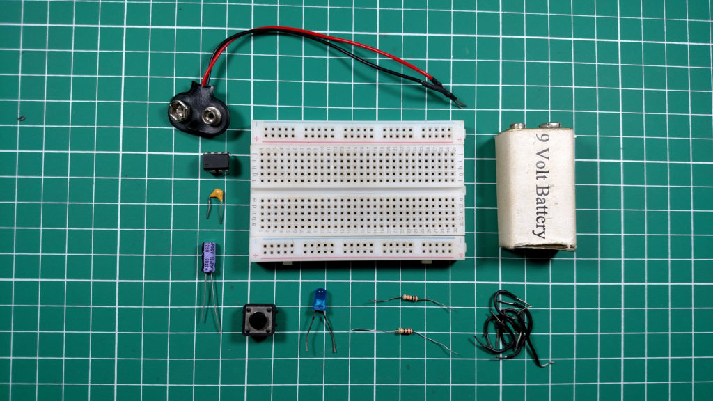
The following components are required to make Monostable Multivibrator Circuit
| S. NO | Component | Value | Qty |
|---|---|---|---|
| 1. | Breadboard | – | 1 |
| 2. | Battery | 9v | 1 |
| 3. | Connecting Wires | – | 1 |
| 4. | IC | NE555 Timer | 1 |
| 5. | Resistors | 100k, 10k, 220 ohms | 1,1,1 |
| 6. | Ceramic Capacitor | 0.01uF | 1 |
| 7. | Electrolytic Capacitor | 1uF | 1 |
| 8. | Push Button | – | 1 |
555 IC Pinout

For a detailed description of pinout, dimension features, and specifications download the datasheet of 555 Timer
Circuit Diagram
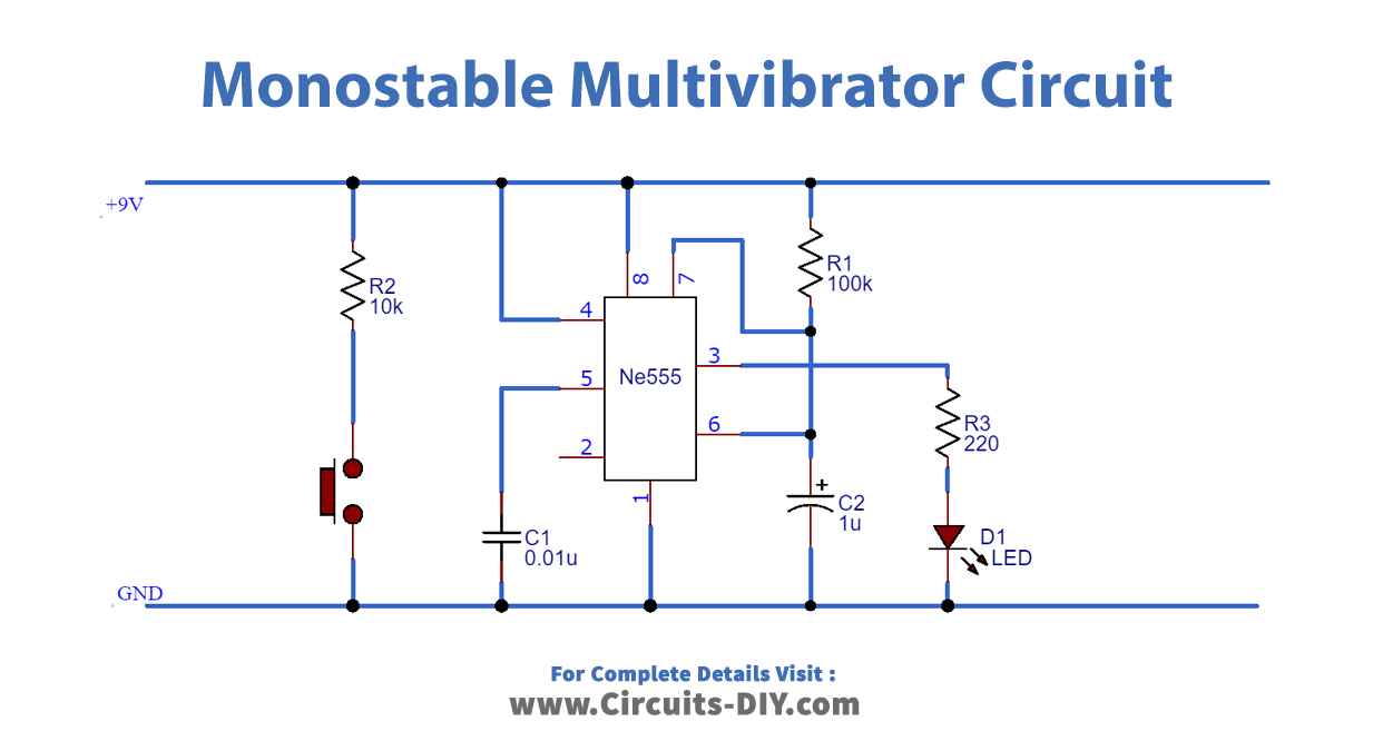
Connection
- Connect Pin 4 & 8 to VCC.
- Connect Pin 1 to GND.
- Add 0.01uF Capacitor at Pin 5.
- Add 1uF Capacitor at Pin 6,
- Use a jumper wire to connect Pin 6 to Pin 7
- Add 100k Ω Resistor at Pin 7.
- Add Push Button at Pin 2 with 10K Ω Resistor.
- Connect LED with 220 Ω Resistor at output Pin 3
Working Explanation
A monostable multivibrator has only one stable state and it generates a single unstable pulse at the output when we apply an external trigger to the IC at Pin 2. The time duration of the unstable state depends on the value of resistors (R1 & R2) and capacitors (C1). In order to view the output of the circuit, we have connected an LED to Pin 3 of the IC. This LED will remain On only for a small duration when we will press the button.
Pin 4 of the IC is connected to VCC, in order to avoid any accidental resets. A negative pulse is applied to Pin 2 of the IC to change the output from Low to High. Pin 5 is the control pin and it is grounded via a capacitor to avoid high-frequency noises.
Application
- We can use them as temporary memory circuits.
- We can use them as a trigger for other pulse generator circuits.