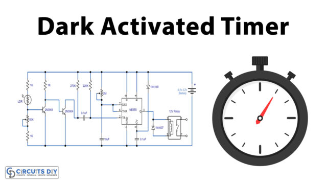
Here we will demonstrate a circuit for a dark detector using 555 timer IC and an LDR that detects light in the area, activating ICs and lights up LEDs connected to the circuit if the lighting is not detected.
We may use a buzzer or a speaker as a dark detector warning instead of an LED. The LDR circuit principle is fundamental and based on the function of the LDR.
Hardware Component
The hardware components required to make a Simple LDR Circuit are:
| S.no | Component | Value | Qty |
|---|---|---|---|
| 1. | IC | NE555 Timer | 1 |
| 2. | Capacitor | 100 nF, 100 uF | 1, 1 |
| 3. | Resistor | 1K, 4.7K, 47K | 1, 1, 1 |
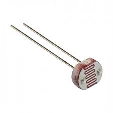
| 4. | LDR | – | 1 |
| 5. | LED | – | 1 |
| 6. | Battery | 9 V | 1 |
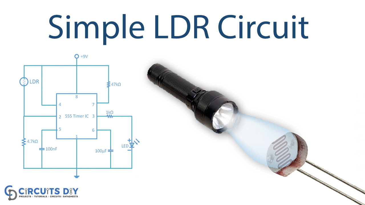
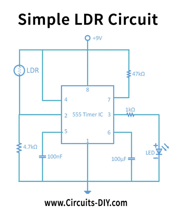
Circuit Diagram
Circuit Operation
The figure above shows the dark detecting LED circuit diagram. It reveals how a basic astable mode can be transformed into a dark sensor. We just have to connect an LDR and a circuit resistor, and then it works as the dark detector.
For the detection of light, a general-purpose LDR is used. LDR’s resistance is very poor when the proper light comes. The LDR resistance increases when no light appears. The IC is activated, and the circuit connected to the LED glows.
Applications and Uses
The LDR Circuit is used in
- Street lights
- Alarm clocks
- Burglar alarm circuits
- Light intensity meters