Introduction
Do you ever worry about your home security when you’re away? What if there was a way to have an extra set of eyes to watch your property and alert you if anything suspicious happens? Well, look no further! This tutorial will show you how to create a simple door security alarm circuit that will give you peace of mind and keep your home safe and secure.
This circuit is easy to build and can be customized to suit your specific needs. So, this tutorial is for you, whether you’re a newbie or an experienced DIY enthusiast. Let’s build a door security alarm to protect your home.
Hardware Required
You will require the following hardware for Simple Door Security Alarm Circuit.
| S.no | Components | Value | Qty |
|---|---|---|---|
| 1 | Capacitors | C1 10nf, C2 10nf, C3 10pf, C4 C6 100nf, | 7 |
| 2 | Diode | D1 D2 D3 D4 1N4148 | 3 |
| 3 | Resistor | R1 1M,R2 3K3, R3 10K, R4 33K, R5 150K, R6 2K2 ,R7 22K, R8 4K7 | 7 |
| 6 | Transistor | Q1 Q2 Q3 Q5 BC547 Q4 BC557 | 5 |
| 7 | Buzzer | Piezo | 1 |
| 8 | LED | RED | 1 |
| 9 | Battery | 9v | 1 |
| 10 | Switch | SW1 SW2 SPST | 2 |
| 11 | Inductor | L1 L2 10mH | 2 |
Circuit Diagram
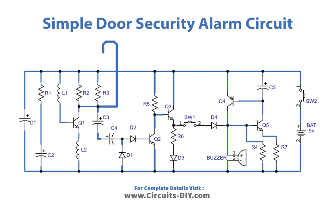
- L1 is put together winding 20 to 30 winding of 0.4mm. Diameter enameled copper wire on the R2 component and soldered the coil terminals to the resistor pins.
- R2 components should be packed thoroughly with coil winding.
- The hook-up is formed from a non-insulated cable 1 – 2mm. Diameter (brass is a good choice).
Testing
The door must be closed before you attach the hook and turn on the circuit by pressing SW1. Adjust R3 an until the LED just lights up, and then back it off gradually till it goes dark. Now, when you put your palm on the door handle, an LED should turn on and turn off again when your hand is removed. Finally, push SW1 to activate the beeper’s loud signal; the door handle may then be used normally until SW2 is turned off. In a typical setup, when the call is over, SW1 is opened and the device is turned on. Avoid accidental beeper activation by taking this precaution.
Working Explanation
The Simple Door Security Alarm Circuit is a circuit that is designed to produce a beep and light up a LED when a person hits the door handle from outside. The circuit is encapsulated in a compact plastic or timber container. It must be hung up to the door handle using a thick cable link overhanging from the container’s apex. The circuit has a wide-range level of responsiveness regulation that allows the application of the Door Alarm over a wide selection of door categories, grips, and locking systems.
- The circuit uses Q1 to form a free-running oscillator. The output bursts drive Q2 into saturation. Thus Q3 and the LED are off.
- When a person’s body comes in contact with a metallic handle that is electrically attached to the cord hook, the human body capacitance damps Q1 oscillations, Q2 biasing collapses off, and the transistor evolves into non-conducting.
- This causes current to flow into the Q3 base, and D3 lights up.
- If SW1 is closed, a self-latching circuit created by Q4 & Q5 is activated, and the beeper BZ1 is initialized.
- Once the body part triggers the handle, the LED switches off. But the beeper continues to buzz due to the self-latching actions of Q4 & Q5. To discontinue the beeper activity, the whole circuit needs to be switched off by breaking SW2.
- R3 is the sensitivity shaft, controlling various door categories, handles, and locking systems.
Final Words
In conclusion, the Simple Door Security Alarm Circuit is an easy-to-build and effective way to increase the security of your home or office. The circuit is designed to produce a beep and/or light up a LED when a person hits the door handle from outside. The circuit is compact and can be hung up to the door handle using a thick cable link. The sensitivity level of the circuit can be adjusted to suit a wide range of door types, handles, and locking systems. Try this amazing circuit, and if you have any questions, feel free to ask in the comment section.