Introduction
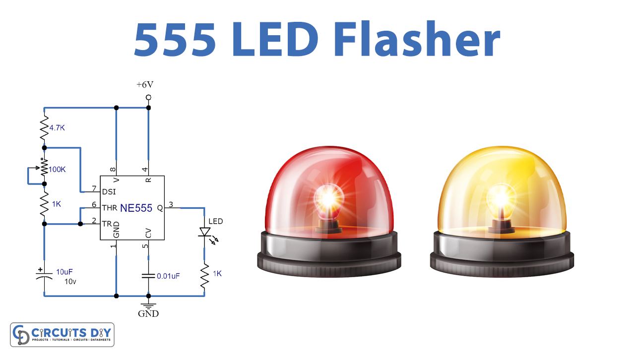
The circuit of the LED flasher is a circuit that flashes the LED and turns it ON and OFF. The chip of 555 timers is used in the circuit of the LED flasher. The chip of the 555 timer is a very flexible Integrated Circuit (IC) because when it is joined appropriately it can generate pulses of current at particular intervals of time decided by the network of capacitors and resistors called the RC network.
When a 555 IC generates pulses in the path of the RC network, the LED does not remain on constantly. It just turns on at a pulse and after the passing of the pulse it shuts off. 555 timer IC does this in a never-finishing sequence and it generates the flashing of light.
Hardware Required
| S.no | Component | Value | Qty |
|---|---|---|---|
| 1. | IC | NE555 Timer | 1 |
| 2. | Resistor | 1K, 10K | 2, 1 |
| 3. | Capacitor | 10uF, 0.01uF | 1, 1 |
| 4. | LED | – | 1 |
| 5. | Battery | 9V | 1 |
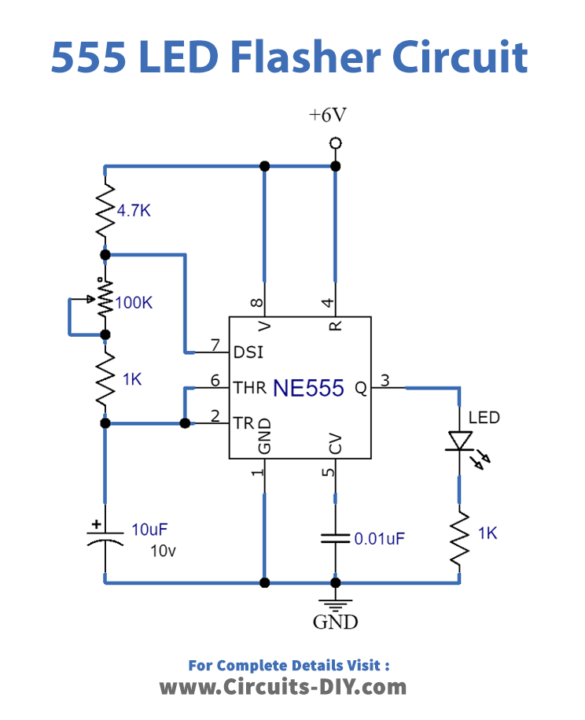
Circuit Diagram
Working Explanation
IC of 555 timers is used to generate a difference in time in several applications. The circuit of flashing LED uses 555 timers in an astable manner, which creates a permanent output at pin three in the form of a square wave. The LED will turn OFF and ON through the waveform. The time period of OFF and ON relies on the cycle of time of the square wave.
Applications and Uses
555 timers have several applications and they are commonly used in the Modulation of Pulse Width (PMW), Fixed oscillators for frequency of variable duty cycle, Timer Switches, Wiper Speech Control, Lamp Dimmers,s, etc.