Introduction
A ceiling fan is among the most typical household appliances. A regulator is required for the ceiling fans to operate. Different types of regulators are available, and different ceiling fans come with different types of regulators. Most people are unconcerned with the regulator, but it is critical to understand that even the regulator may waste power and raise your electricity costs. However, the focus of this article is not on the many sorts of regulators, but rather on the making of the regular circuit. Hence, In this tutorial, we are going to Make a “Ceiling Fan regulator circuit”
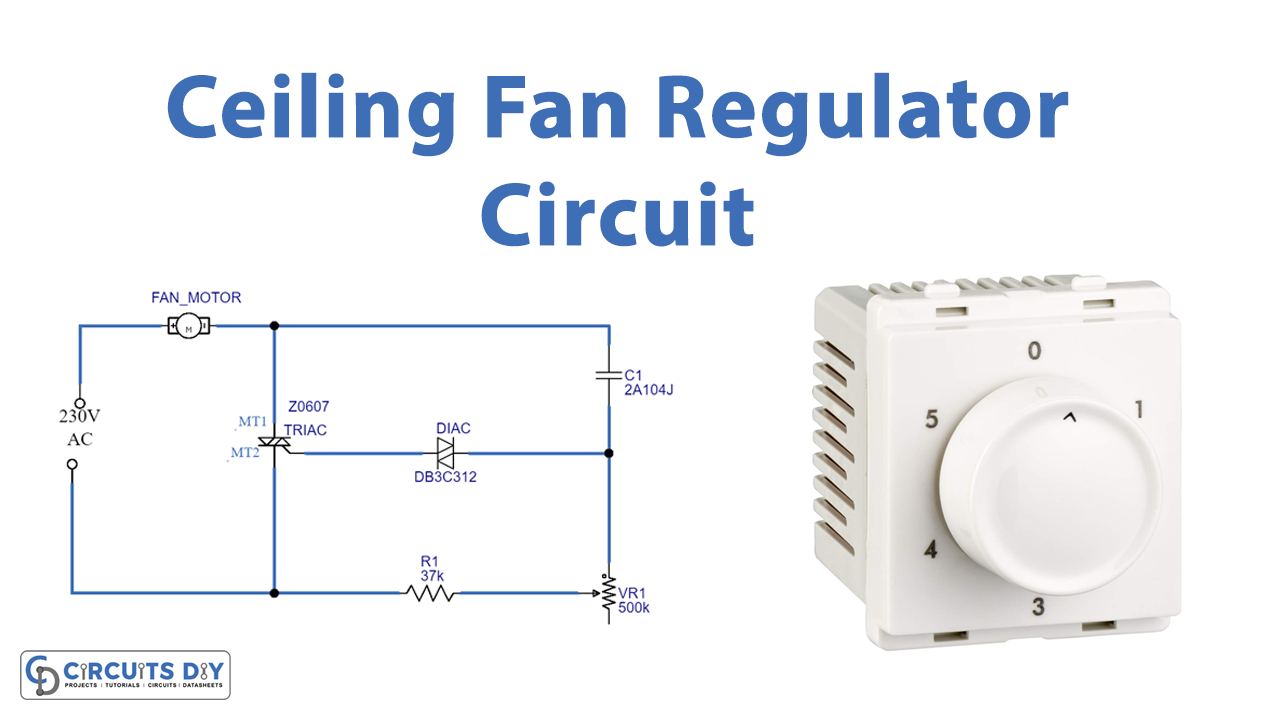
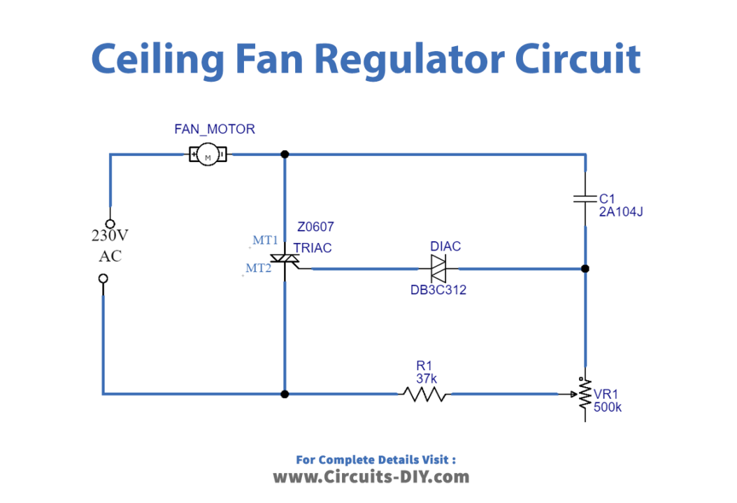
In the making of the circuit, we are not using a regular ceiling fan but a fan motor which you might have seen in various appliances. Along with that, a circuit requires a few basic electronic components including Triac, Diac, and variable resistor components. This regulator circuit smoothly adjusts the ceiling fan speed.
Hardware Required
| S.no | Component | Value | Qty |
|---|---|---|---|
| 1. | Fan Motor | – | 1 |
| 2. | TRIAC | Z0607 | 1 |
| 3. | Potentiometer | 500K | 1 |
| 4. | Capacitor | 2A104J | 1 |
| 5. | Resistor | 37K | 1 |
| 6. | DIAC | C312 | 1 |
Circuit Diagram
Working Explanation
In this Ceiling Fan regulator circuit, the power supply phase line is connected to one terminal of the fan, and the other terminal of the fan is connected to the regulator circuit, which includes a TRIAC connected across the fan and a neutral power line, a DIAC connected to the gate terminal, and a polymer capacitor connected to a potentiometer. These components control the voltage flow through the fan.
Application and Uses
- The circuit is particularly used to control the Ceiling fans.